Abstract: In its simplest form, the PC voltmeter consists of a 4-channel, 10-bit A/D converter (IC2) with a few passive components, connected to the PC printer port via a 25-pin male D-type connector.
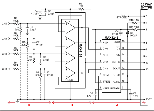
In its simplest form, the PC voltmeter of Figure 1 consists of section "A" alone: a 4-channel, 10-bit A/D converter (IC2) with a few passive components, connected to the PC printer port via a 25-pin male D-type connector. Power is derived from pins 2 and 3, and the circuit draws about 1mA.
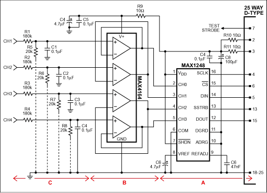
Figure 1. This circuit and the associated Q-BASIC listing enable a PC to monitor and measure the voltages on four input channels.
IC2's wide power-supply range (2.7V to 5.25V) allows operation from a variety of PC printer ports. The voltage at pins 2 and 3 is about 5V for a lot of desktop machines, but for portables it is more likely to be around 3V. IC2 handles them all. R10-R11 and C7-C8 filter the PC noise from this supply line. C6 and C9 decouple the 2.5V reference internal to IC2.
To maintain 10-bit accuracy, the source impedances driving the ADC inputs (pins 2-5) must be less than 3kΩ. If not, you can buffer these inputs by adding the "B" section to the circuit. This quad op amp (configured as four noninverting buffers) has rail-to-rail inputs and outputs, operates with supply voltages down to 2.7V, and draws about 25μA per amplifier.
To provide high-voltage protection, the op amps' very low bias current (1pA typical) allows 180kΩ resistors in series with each input without introducing excessive error (R1-R4 in section "C"). For additional (anti-aliasing) filtering you can add capacitors C1-C4, and to increase the full-scale range from 2.5V to 25V you can add R5-R8.
Other variations: You can substitute a 12-bit MAX1246 for IC2 in place of the 10-bit MAX1248, but for 12-bit accuracy you must restrict the supply voltage to the range 2.7V to 3.6V. Alternatively, you can substitute a 12-bit MAX1247 and add an external reference such as the MAX872, which gives a 2.5V output for input voltages down to 2.7V.
Two Q-BASIC listings are available, each written for the 12-bit circuit options. Listing 1 scans the four channels and displays each input voltage on the screen. Listing 2 displays the channel voltages, plots them vs. time on the screen, and lets you save the data to disk.
In its simplest form, the PC voltmeter of Figure 1 consists of section "A" alone: a 4-channel, 10-bit A/D converter (IC2) with a few passive components, connected to the PC printer port via a 25-pin male D-type connector. Power is derived from pins 2 and 3, and the circuit draws about 1mA.

Figure 1. This circuit and the associated Q-BASIC listing enable a PC to monitor and measure the voltages on four input channels.
IC2's wide power-supply range (2.7V to 5.25V) allows operation from a variety of PC printer ports. The voltage at pins 2 and 3 is about 5V for a lot of desktop machines, but for portables it is more likely to be around 3V. IC2 handles them all. R10-R11 and C7-C8 filter the PC noise from this supply line. C6 and C9 decouple the 2.5V reference internal to IC2.
To maintain 10-bit accuracy, the source impedances driving the ADC inputs (pins 2-5) must be less than 3kΩ. If not, you can buffer these inputs by adding the "B" section to the circuit. This quad op amp (configured as four noninverting buffers) has rail-to-rail inputs and outputs, operates with supply voltages down to 2.7V, and draws about 25μA per amplifier.
To provide high-voltage protection, the op amps' very low bias current (1pA typical) allows 180kΩ resistors in series with each input without introducing excessive error (R1-R4 in section "C"). For additional (anti-aliasing) filtering you can add capacitors C1-C4, and to increase the full-scale range from 2.5V to 25V you can add R5-R8.
Other variations: You can substitute a 12-bit MAX1246 for IC2 in place of the 10-bit MAX1248, but for 12-bit accuracy you must restrict the supply voltage to the range 2.7V to 3.6V. Alternatively, you can substitute a 12-bit MAX1247 and add an external reference such as the MAX872, which gives a 2.5V output for input voltages down to 2.7V.
Two Q-BASIC listings are available, each written for the 12-bit circuit options. Listing 1 scans the four channels and displays each input voltage on the screen. Listing 2 displays the channel voltages, plots them vs. time on the screen, and lets you save the data to disk.
 電子發燒友App









評論