The design of integrated linear regulators for battery applications is full of difficult compromises. Designs must deliver low operating current for long-battery life while supplying clean, well-regulated power in a sometimes noisy environment. This note describes techniques for improving the rejection of AC artifacts while maintaining low operating current.
Challenges
Regulator operating currents of less than 250μA limit the available gain-bandwidth, making specifications such as noise, regulation, and power supply rejection tricky to achieve.In portable communications, low-dropout linear regulators (LDOs) are used to generate supply voltages for the RF circuitry; these voltages must be especially clean when powering the synthesizer and VCO. The supply that powers the regulator often includes wideband AC ripple superimposed on the DC. The LDO is expected to reject these artifacts.
When an LDO is powered by a switching regulator, it must be able to cope with switching frequencies beyond 300kHz.
Designers expect these capabilities without an increase in the LDO's quiescent current.
Line Regulation
There are two specifications in the LDO data sheet that refer to the LDO's ability to reject the various forms of noise on the incoming supply. They are line regulation and power-supply rejection ratio (PSRR).Line regulation measures the ability of the LDO to ignore changes of input voltage. Mathematically,

In practice, line regulation is referred to the regulator output voltage in terms of %/VOUT. This is particularly useful when the same regulator is available with numerous output voltage trim options.

Line regulation is a steady-state DC measurement, and is a measure of the regulator open-loop current gain at zero frequency.
Power Supply Rejection Ratio
This specification is the measure of how well the regulator rejects an AC signal riding on a nominal input DC voltage.
Power-supply rejection ratio is at a maximum at low frequencies, and begins to fall above 1kHz to 10kHz, depending upon the regulator design. Figure 1 shows the PSRR typical characteristic for the MAX8867 150mA low-noise LDO, and Figure 2 shows the PSRR characteristic for the MAX1792 500mA LDO.

Figure 1. MAX8867 PSRR characteristic.
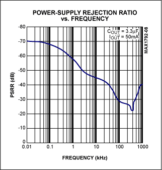
Figure 2. MAX1792 PSRR characteristic.
The only way to modify the basic rejection response of the regulator is to add an external network at the input of the regulator.
External Networks
There are three methods to choose from:1. One or more cascades of external RC filters. The additional attenuation adds to the inherent characteristic of the regulator. The series resistor(s) has to be kept low in order to minimize the IR losses and consequent reduction of regulator headroom. This limitation requires that large bulk capacitors be used in association with 1Ω to 10Ω resistors. If the load current is very low, say less than 20mA, then an RC filter is useful.On the other hand, if there is plenty of voltage headroom, and space to dissipate heat, then an RC filter(s) may also be practical for larger load currents. The upper limit for series resistance is defined by the stability of the regulator. The designer assumes a low source impedance for the input supply. A series R greater than 200Ω is entering dangerous territory.
The low-pass-filter transfer characteristic for a single RC is

Its attenuation characteristic is -20dB / decade from the corner frequency f = (2π RC)-1. Ultimate attenuation is given by

The transfer characteristic of a second-order cascade low-pass filter with equal-value Rs and Cs is

Attenuation characteristic is -40dB / decade from a corner frequency f = (2π RC)-1. Ultimate attenuation is double that of the single-order network, assuming CESR<
Typical values for the single RC and cascade RC filters range from R=1Ω to 10Ω, and C=100μF to 10μF respectively. Choose the network -3dB frequency to coincide with that of the regulator PSRR characteristic.
Figure 3a shows the single order RC network, and Figure 3b shows the cascade second-order RC network, both protecting a linear regulator.
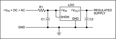
Figure 3a. Single RC ripple filter.
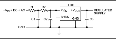
Figure 3b. Second-order cascade RC ripple filter.
2. An LC filter. The problem with using this type of filter is the lack of inherent damping at the output of the network (input of the regulator). The source impedance of the network is low. However, the regulator's VIN terminal presents a high impedance shunted with a small capacitor. (When the regulator is operated away from dropout with a constant load, its input current does not vary, to first order, when VIN is varied.) It is impossible to critically damp the LC network at the input of the regulator without significant DC loss in the shunt damping resistor. For example, a series 10μH inductor in combination with a shunt 100μF capacitor exhibits a turnover frequency of 5kHz; this combination requires a critical damping resistor of 0.32Ω between network output (regulator input) and ground. Figure 4a illustrates the problem.
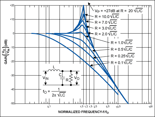
Figure 4a. LC filter amplitude characteristic for various damping ratios.
Figure 4b shows the damping resistor and its relationship with the noisy incoming supply source resistance.

Figure 4b. Illustrating the position of damping resistor.
3. An additional linear regulator. This method occupies a small PCB area (e.g., two SOT23-5 packages) and requires the least design time of the other methods. Using two linear regulators in series doubles the PSRR at any given frequency (assuming identical regulators). The "penalty" for this approach is the doubling of the dropout voltage and the need for an additional capacitor. A good design choice is to share the voltage drop across each regulator. Two MAX8867 regulators in series provide at least 80dB of PSRR at 100kHz, and the total assembly requires three 1μF ceramic capacitors, one each at the input, output, and the intermediate position. Figure 5 shows two linear regulators cascaded in this manner.

Figure 5. Series cascade of LDOs for input ripple isolation.
A MAX8875 (LDO1) followed by a MAX8867 (LDO2) gives a low-noise output and 70dB of PSRR at 100kHz. All capacitors are 1μF.
High-Output-Current Regulator Protection
The previous examples and techniques have focused on low-current single-package LDOs. An RC filter may be added to a high-output-current LDO and produce excellent results with little or no additional IR drop. For this high-current LDO, thermal constraints place the series power transistor outside the main control IC. The supply to the control IC is a fraction of the main current path. Therefore the control-IC power supply is an ideal place to add RC ripple filtering. Figure 6 shows an example employing the MAX687-9 family of 4A LDO regulator controllers.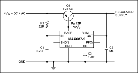
Figure 6. Additional protection for high current LDO.
The supply current at the IN terminal of the MAX687-9 is 250μA. The addition of R1 provides additional filtering to the whole control circuit and enhances the overall circuit PSRR to better than 60dB at 100kHz.
Conclusion
An external network added to the input of a linear regulator improves the inherent PSRR of the LDO, especially at high frequencies, where the low quiescent current compromises the high-frequency PSRR of the LDO.Of the methods outlined above, the additional LDO is the most general purpose, packs more attenuation into a given small area, and requires the least design time.
For low-current applications requiring only modest protection, the RC filter method is cost competitive, but requires careful tradeoffs in component selection.
For high-current LDO controllers, the addition of one resistor to the controller input supply very effectively enhances the PSRR of the entire circuit.
 電子發(fā)燒友App







評論