概述
LSM303分支板結(jié)合了磁力計/羅盤模塊和三軸加速度計,構(gòu)成了緊湊的導航子系統(tǒng)。 I2C接口與3.3v和5v處理器兼容,并且兩個引腳可以由其他I2C設備共享。結(jié)合L3GD20等3軸陀螺儀,您將擁有完整的IMU(慣性測量單元)所需的所有傳感器,以用于空中,陸地或海洋導航。
在本教程中,我們將向您展示如何將LSM303連接到Arduino,CircuitPython開發(fā)板或Blinka支持的設備,以及如何使用它來測量相對于地球磁場的方向以及在三個軸上的加速度。
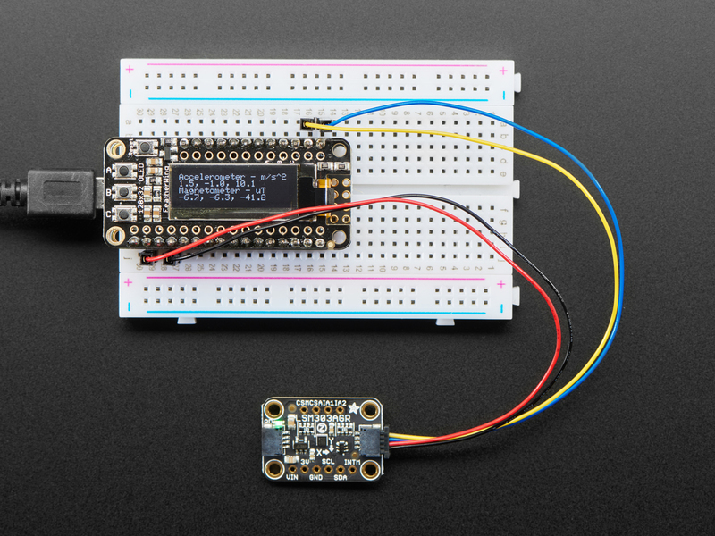
新版LSM303AGR的一個重要功能是它包括一個 STEMMA QT 連接器,無需焊接即可使用。 只需將STEMMA QT插入公頭連接線,即可將其連接到帶有母頭的面包板或開發(fā)板,重新參加比賽!您甚至可以使用STEMMA QT電纜將其與其他STEMMA QT分支連接起來
i》
工作原理:
傳感器組成硅晶片上的微機械結(jié)構(gòu)。有一些用于測量X,Y和Z軸上的加速度和磁場的結(jié)構(gòu)
加速度測量
這些結(jié)構(gòu)被多晶硅彈簧懸掛,當它們在X,Y和/或Z軸上受加速度作用時,它們可以偏轉(zhuǎn)。撓曲會導致固定板和連接到懸掛結(jié)構(gòu)的板之間的電容發(fā)生變化。每個軸上的電容變化都會轉(zhuǎn)換為與該軸上的加速度成比例的輸出電壓。
磁場測量
這些結(jié)構(gòu)與加速度計的結(jié)構(gòu)相似,但是用微觀線圈蝕刻。勵磁電流流經(jīng)線圈,由于磁場而產(chǎn)生的洛倫茲力使結(jié)構(gòu)發(fā)生偏轉(zhuǎn)。偏轉(zhuǎn)再次轉(zhuǎn)換為與該軸上的磁場強度成比例的輸出電壓。
我擁有哪個LSM303?
現(xiàn)在有兩個由Adafruit制造的LSM303突破口! Schnikes!它們的功能幾乎相同,但又有足夠的差異,以至于它們需要磁力計的不同驅(qū)動器。為什么只有磁力計?好吧,我要告訴你一個小秘密:LSM303是兩個傳感器貼在同一個盒子里!
因為兩個封裝都具有相同的加速度傳感器,且寄存器布局相同,所以我們可以使用兩者都使用相同的加速度計驅(qū)動器。磁力計盡管都具有相同的I2C地址(0x1E),但寄存器布局卻完全不同,這意味著它們各自需要自己的驅(qū)動程序庫。
因此,您將需要知道你有哪個版本。這是區(qū)分兩個 Adafruit 突破的一種高度科學的方法:
LSM303AGR是黑色的,說“ LSM303AGR”不同于
LSM303DLHC是藍色并且說“ LSM303DLHC”
復雜,我知道,但我相信您。下面概述了更多細微的差異
LSM303AGR
adafruit塊上的新孩子是LSM303AGR。這是對LSM303系列的更新,該系列體積更小,內(nèi)部裝有不同的磁力計芯片。我們的突破如下:
除了體積更小,更容易丟失籌碼外,還有其他一些區(qū)別。芯片本身暴露了磁力計(INTM)的中斷引腳(也許是內(nèi)置的新型磁力計傳感器的功能?)以及加速度計和磁力計的芯片選擇引腳( CSA 和 CSM )。
兩者之間的另一個令人興奮的區(qū)別是增加了兩個 STEMMA QT 連接器,每個連接器的一側(cè)板。這樣一來,您無需焊接即可使用該傳感器,并且可以與其他STEMMA QT傳感器鏈接。
請注意,雖然LSM303AGR分支具有CS引腳,但它僅支持3線SPI,而我們無法使用它。喜歡冒險的人可以參考數(shù)據(jù)表并嘗試一下!歡迎PR;)
LSM303/LSM303DLHC
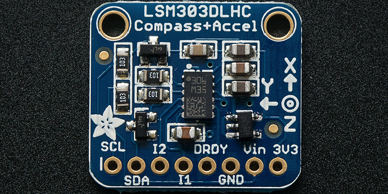
AdafruitLSM303分支使用LSM303 DLHC ,看起來像這樣:
》
與LSM303AGR相比,您可以看到傳感器本身(中間的黑色矩形)實際上更大。此外,引腳的順序不同,并且LSM303DLH公開了 DRDY (數(shù)據(jù)就緒)引腳。
插腳

電源引腳
Vin -這是電源引腳。由于傳感器芯片使用的是3.3 VDC,因此我們在板載了一個穩(wěn)壓器,該穩(wěn)壓器將采用3-5VDC的電壓并將其安全地向下轉(zhuǎn)換。要為電路板供電,請為其提供與微控制器邏輯電平相同的功率-例如,對于像Arduino這樣的5V微控制器,請使用5V
3Vo -這是穩(wěn)壓器的3.3V輸出,如果您愿意,可以從中獲得100mA的電流。
GND -電源和邏輯的公共接地
I2C邏輯引腳
SCL -I2C時鐘引腳,連接到微控制器的I2C時鐘線。該引腳經(jīng)過電平轉(zhuǎn)換,因此您可以使用3-5V邏輯,并且該引腳上具有 10K上拉。
SDA -I2C數(shù)據(jù)引腳,連接到微控制器的I2C數(shù)據(jù)線。該引腳經(jīng)過電平轉(zhuǎn)換,因此您可以使用3-5V邏輯,并且該引腳上具有 10K上拉。
STEMMA QT- ,這些連接器允許您可以連接到具有 STEMMA QT 連接器的開發(fā)板或具有各種關聯(lián)附件的其他東西的連接器
其他通用引腳
IA1 -加速度計的第一個中斷引腳。僅限3V邏輯
IA2-加速度計的第二個中斷引腳。僅3V邏輯
LSM303AGR僅限
INTM -磁力計的中斷引腳。僅限3V邏輯
CSA-加速度計的CS引腳。僅限3V邏輯
CSM-磁力計的CS引腳。僅限3V邏輯
請注意,雖然LSM303AGR突破口具有CS引腳,僅支持我們無法使用的3線SPI。喜歡冒險的人可以參考數(shù)據(jù)表并嘗試一下!歡迎PR;)
僅適用于LSM303DLH
DRDY -這是數(shù)據(jù)就緒引腳。僅限3V邏輯
程序集
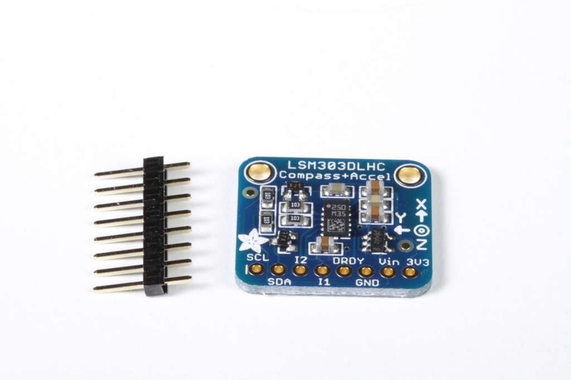
電路板組裝:所有表面安裝組件都已預先焊接到電路板上。您可以將連接直接焊接到板上,也可以安裝標題欄(已提供)以簡化在面包板上的使用。

放置頁眉,如有必要,將頁眉切成一定長度,然后將長針向下插入面包板。
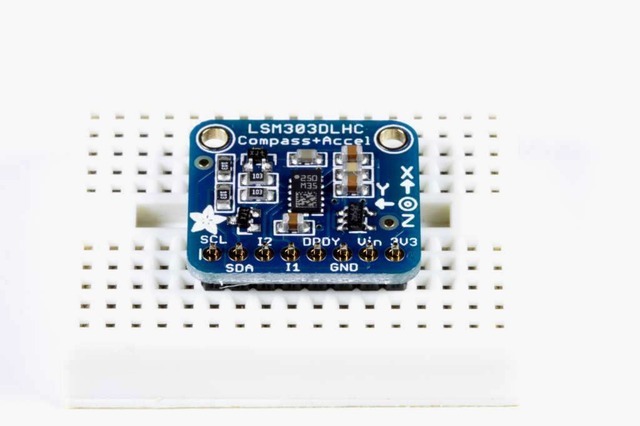
放置板子將板子放在排針頂部。支撐必要的背面,以便在焊接之前將電路板弄平。
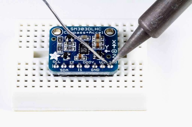
然后焊接!焊接每個引腳以確保良好的電氣連接。
如果您是焊接新手,請查閱我們的出色焊接指南。
Arduino
Arduino接線
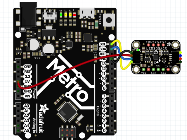
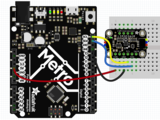
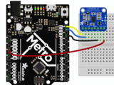
Connect 板載VCC(紅線)5V Arduino板(Uno等),則將strong》改為 Arduino 5V 。如果您的板為 3V, 相反。
連接板子 GND(黑線)到 Arduino GND
將板 SCL(黃線)連接到 Arduino SCL
連接板 SDA(藍線)到 Arduino SDA
ul》
安裝庫
要開始使用LSM303,您需要安裝加速度計庫,并板的磁力計庫。另外,您將需要Adafruit_Sensor庫以及Adafruit_BusIO庫,該庫允許它以與其他類似傳感器一致的方式返回數(shù)據(jù)。可以使用Arduino IDE中的庫管理器安裝所有庫:
在繼續(xù)之前,請確保您知道傳感器的版本,
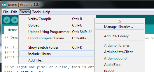
安裝加速計庫
點擊管理庫。.. 菜單項,搜索 Adafruit LSM303 Accel ,然后選擇 Adafruit_LSM303_Accel 庫:

安裝磁力計庫
最后,您需要在LSM303中安裝磁力計庫。確保下載適用于您的分組討論板的正確驅(qū)動程序。
LSM303AGR
在庫管理器中搜索 Adafruit_LSM303AGR_Mag 庫:

LSM303/LSM303DLHC
在庫管理器中搜索 Adafruit_LSM303DLH_Mag 庫:

安裝幫助程序庫
對 Adafruit BusIO 庫執(zhí)行相同的過程:

最后,對 Adafruit Unified Sensor 庫:

加速度計演示
第一個演示將向您展示如何獲得加速度計最有效的讀數(shù):測量加速度!
打開文件-》示例-》 Adafruit LSM303 Accel -》 accelsensor 并上傳到與傳感器連接的Arduino。
將草圖上傳到板上并打開Serial Monitor(工具-》 Serial Monitor )以 115200波特。您應該看到啟動時打印的當前配置設置的值,然后是與X,Y和Z軸類似的加速度讀數(shù):

Adafruit_LSM303_Accel_Unified 傳感器Adafruit_LSM303_Accel庫中的類報告X,Y和Z軸加速度計的讀數(shù)直接以米/秒為平方。庫中的accelsensor示例代碼從傳感器讀取并將加速度讀數(shù)打印到串行監(jiān)視器中。
在靜止狀態(tài)下,傳感器不應報告任何加速度,除非是由于重力(大約9.8米/秒平方)。通過計算重力矢量相對于X,Y和Z軸的角度,該設備可以用作傾角儀。
基本磁力計讀數(shù)
第一個演示將向您展示如何獲得加速度計最有效的讀數(shù):測量加速度!
LSM303AGR
打開文件-》示例-》 Adafruit LSM303AGR Mag -》磁傳感器并上傳到您的Arduino接線端
LSM303/LSM303DLH
打開文件-》示例-》 Adafruit LSM303DLH Mag -》磁傳感器,然后
將草圖上傳到您的電路板上,并以 115200波特打開串行監(jiān)視器(工具-》串行監(jiān)視器)。您應該看到啟動時打印的當前配置設置的值,然后是X,Y和Z軸的磁場讀數(shù),類似于:

磁力儀庫中的傳感器類報告X,Y和Z軸磁力儀讀數(shù)直接在微型Teslas中。 magsensor 示例代碼從傳感器讀取并將微型特斯拉讀數(shù)打印到串行監(jiān)視器。
在沒有任何強磁場的情況下,傳感器讀數(shù)應反映地球的磁場(介于20到60微特拉斯之間)。當傳感器保持水平時,通過計算磁場相對于X和Y軸的角度,該設備可用作指南針。
計算指南針航向
要將microTesla讀數(shù)轉(zhuǎn)換為0-360度指南針航向,我們可以使用atan2()函數(shù)來計算由Y和X軸讀數(shù)定義的向量的角度。結(jié)果將以弧度為單位,因此我們將其乘以180度并除以Pi以將其轉(zhuǎn)換為度。
LSM303AGR
打開文件-》示例-》 Adafruit LSM303AGR Mag -》羅盤,并上傳到與傳感器連接的Arduino。
LSM303/LSM303DLH
打開文件-》示例-》 Adafruit LSM303DLH Mag -》羅盤,并通過傳感器連接到Arduino。
將草圖上傳到板上并打開串行監(jiān)視器(工具-》串行監(jiān)視器),位于 115200波特。您將看到航向計算打印到串行監(jiān)視器。如果在傳感器運行時旋轉(zhuǎn)傳感器,則會看到航向更改:

加速度計演示代碼
下載:Project Zip 或 accelsensor.ino | 在Github上查看
復制代碼
#include
#include
#include
/* Assign a unique ID to this sensor at the same time */
Adafruit_LSM303_Accel_Unified accel = Adafruit_LSM303_Accel_Unified(54321);
void displaySensorDetails(void) {
sensor_t sensor;
accel.getSensor(&sensor);
Serial.println(“------------------------------------”);
Serial.print(“Sensor: ”);
Serial.println(sensor.name);
Serial.print(“Driver Ver: ”);
Serial.println(sensor.version);
Serial.print(“Unique ID: ”);
Serial.println(sensor.sensor_id);
Serial.print(“Max Value: ”);
Serial.print(sensor.max_value);
Serial.println(“ m/s^2”);
Serial.print(“Min Value: ”);
Serial.print(sensor.min_value);
Serial.println(“ m/s^2”);
Serial.print(“Resolution: ”);
Serial.print(sensor.resolution);
Serial.println(“ m/s^2”);
Serial.println(“------------------------------------”);
Serial.println(“”);
delay(500);
}
void setup(void) {
#ifndef ESP8266
while (!Serial)
; // will pause Zero, Leonardo, etc until serial console opens
#endif
Serial.begin(9600);
Serial.println(“Accelerometer Test”);
Serial.println(“”);
/* Initialise the sensor */
if (!accel.begin()) {
/* There was a problem detecting the ADXL345 。.. check your connections */
Serial.println(“Ooops, no LSM303 detected 。.. Check your wiring!”);
while (1)
;
}
/* Display some basic information on this sensor */
displaySensorDetails();
accel.setRange(LSM303_RANGE_4G);
Serial.print(“Range set to: ”);
lsm303_accel_range_t new_range = accel.getRange();
switch (new_range) {
case LSM303_RANGE_2G:
Serial.println(“+- 2G”);
break;
case LSM303_RANGE_4G:
Serial.println(“+- 4G”);
break;
case LSM303_RANGE_8G:
Serial.println(“+- 8G”);
break;
case LSM303_RANGE_16G:
Serial.println(“+- 16G”);
break;
}
accel.setMode(LSM303_MODE_NORMAL);
Serial.print(“Mode set to: ”);
lsm303_accel_mode_t new_mode = accel.getMode();
switch (new_mode) {
case LSM303_MODE_NORMAL:
Serial.println(“Normal”);
break;
case LSM303_MODE_LOW_POWER:
Serial.println(“Low Power”);
break;
case LSM303_MODE_HIGH_RESOLUTION:
Serial.println(“High Resolution”);
break;
}
}
void loop(void) {
/* Get a new sensor event */
sensors_event_t event;
accel.getEvent(&event);
/* Display the results (acceleration is measured in m/s^2) */
Serial.print(“X: ”);
Serial.print(event.acceleration.x);
Serial.print(“ ”);
Serial.print(“Y: ”);
Serial.print(event.acceleration.y);
Serial.print(“ ”);
Serial.print(“Z: ”);
Serial.print(event.acceleration.z);
Serial.print(“ ”);
Serial.println(“m/s^2”);
/* Delay before the next sample */
delay(500);
}
#include
#include
#include
/* Assign a unique ID to this sensor at the same time */
Adafruit_LSM303_Accel_Unified accel = Adafruit_LSM303_Accel_Unified(54321);
void displaySensorDetails(void) {
sensor_t sensor;
accel.getSensor(&sensor);
Serial.println(“------------------------------------”);
Serial.print(“Sensor: ”);
Serial.println(sensor.name);
Serial.print(“Driver Ver: ”);
Serial.println(sensor.version);
Serial.print(“Unique ID: ”);
Serial.println(sensor.sensor_id);
Serial.print(“Max Value: ”);
Serial.print(sensor.max_value);
Serial.println(“ m/s^2”);
Serial.print(“Min Value: ”);
Serial.print(sensor.min_value);
Serial.println(“ m/s^2”);
Serial.print(“Resolution: ”);
Serial.print(sensor.resolution);
Serial.println(“ m/s^2”);
Serial.println(“------------------------------------”);
Serial.println(“”);
delay(500);
}
void setup(void) {
#ifndef ESP8266
while (!Serial)
; // will pause Zero, Leonardo, etc until serial console opens
#endif
Serial.begin(9600);
Serial.println(“Accelerometer Test”);
Serial.println(“”);
/* Initialise the sensor */
if (!accel.begin()) {
/* There was a problem detecting the ADXL345 。.. check your connections */
Serial.println(“Ooops, no LSM303 detected 。.. Check your wiring!”);
while (1)
;
}
/* Display some basic information on this sensor */
displaySensorDetails();
accel.setRange(LSM303_RANGE_4G);
Serial.print(“Range set to: ”);
lsm303_accel_range_t new_range = accel.getRange();
switch (new_range) {
case LSM303_RANGE_2G:
Serial.println(“+- 2G”);
break;
case LSM303_RANGE_4G:
Serial.println(“+- 4G”);
break;
case LSM303_RANGE_8G:
Serial.println(“+- 8G”);
break;
case LSM303_RANGE_16G:
Serial.println(“+- 16G”);
break;
}
accel.setMode(LSM303_MODE_NORMAL);
Serial.print(“Mode set to: ”);
lsm303_accel_mode_t new_mode = accel.getMode();
switch (new_mode) {
case LSM303_MODE_NORMAL:
Serial.println(“Normal”);
break;
case LSM303_MODE_LOW_POWER:
Serial.println(“Low Power”);
break;
case LSM303_MODE_HIGH_RESOLUTION:
Serial.println(“High Resolution”);
break;
}
}
void loop(void) {
/* Get a new sensor event */
sensors_event_t event;
accel.getEvent(&event);
/* Display the results (acceleration is measured in m/s^2) */
Serial.print(“X: ”);
Serial.print(event.acceleration.x);
Serial.print(“ ”);
Serial.print(“Y: ”);
Serial.print(event.acceleration.y);
Serial.print(“ ”);
Serial.print(“Z: ”);
Serial.print(event.acceleration.z);
Serial.print(“ ”);
Serial.println(“m/s^2”);
/* Delay before the next sample */
delay(500);
}
LSM303AGR磁力計和指南針代碼
下載:Project Zip 或 magsensor.ino | 在Github上查看
復制代碼
#include
#include
#include
/* Assign a unique ID to this sensor at the same time */
Adafruit_LSM303AGR_Mag_Unified mag = Adafruit_LSM303AGR_Mag_Unified(12345);
void displaySensorDetails(void) {
sensor_t sensor;
mag.getSensor(&sensor);
Serial.println(“------------------------------------”);
Serial.print(“Sensor: ”);
Serial.println(sensor.name);
Serial.print(“Driver Ver: ”);
Serial.println(sensor.version);
Serial.print(“Unique ID: ”);
Serial.println(sensor.sensor_id);
Serial.print(“Max Value: ”);
Serial.print(sensor.max_value);
Serial.println(“ uT”);
Serial.print(“Min Value: ”);
Serial.print(sensor.min_value);
Serial.println(“ uT”);
Serial.print(“Resolution: ”);
Serial.print(sensor.resolution);
Serial.println(“ uT”);
Serial.println(“------------------------------------”);
Serial.println(“”);
delay(500);
}
void setup(void) {
#ifndef ESP8266
while (!Serial)
; // will pause Zero, Leonardo, etc until serial console opens
#endif
Serial.begin(115200);
Serial.println(“Magnetometer Test”);
Serial.println(“”);
/* Enable auto-gain */
mag.enableAutoRange(true);
/* Initialise the sensor */
if (!mag.begin()) {
/* There was a problem detecting the LSM303 。.. check your connections */
Serial.println(“Ooops, no LSM303AGR detected 。.. Check your wiring!”);
while (1)
;
}
/* Display some basic information on this sensor */
displaySensorDetails();
}
void loop(void) {
/* Get a new sensor event */
sensors_event_t event;
mag.getEvent(&event);
/* Display the results (magnetic vector values are in micro-Tesla (uT)) */
Serial.print(“X: ”);
Serial.print(event.magnetic.x);
Serial.print(“ ”);
Serial.print(“Y: ”);
Serial.print(event.magnetic.y);
Serial.print(“ ”);
Serial.print(“Z: ”);
Serial.print(event.magnetic.z);
Serial.print(“ ”);
Serial.println(“uT”);
/* Note: You can also get the raw (non unified values) for */
/* the last data sample as follows. The .getEvent call populates */
/* the raw values used below. */
// Serial.print(“X Raw: ”); Serial.print(mag.raw.x); Serial.print(“ ”);
// Serial.print(“Y Raw: ”); Serial.print(mag.raw.y); Serial.print(“ ”);
// Serial.print(“Z Raw: ”); Serial.print(mag.raw.z); Serial.println(“”);
/* Delay before the next sample */
delay(500);
}
#include
#include
#include
/* Assign a unique ID to this sensor at the same time */
Adafruit_LSM303AGR_Mag_Unified mag = Adafruit_LSM303AGR_Mag_Unified(12345);
void displaySensorDetails(void) {
sensor_t sensor;
mag.getSensor(&sensor);
Serial.println(“------------------------------------”);
Serial.print(“Sensor: ”);
Serial.println(sensor.name);
Serial.print(“Driver Ver: ”);
Serial.println(sensor.version);
Serial.print(“Unique ID: ”);
Serial.println(sensor.sensor_id);
Serial.print(“Max Value: ”);
Serial.print(sensor.max_value);
Serial.println(“ uT”);
Serial.print(“Min Value: ”);
Serial.print(sensor.min_value);
Serial.println(“ uT”);
Serial.print(“Resolution: ”);
Serial.print(sensor.resolution);
Serial.println(“ uT”);
Serial.println(“------------------------------------”);
Serial.println(“”);
delay(500);
}
void setup(void) {
#ifndef ESP8266
while (!Serial)
; // will pause Zero, Leonardo, etc until serial console opens
#endif
Serial.begin(115200);
Serial.println(“Magnetometer Test”);
Serial.println(“”);
/* Enable auto-gain */
mag.enableAutoRange(true);
/* Initialise the sensor */
if (!mag.begin()) {
/* There was a problem detecting the LSM303 。.. check your connections */
Serial.println(“Ooops, no LSM303AGR detected 。.. Check your wiring!”);
while (1)
;
}
/* Display some basic information on this sensor */
displaySensorDetails();
}
void loop(void) {
/* Get a new sensor event */
sensors_event_t event;
mag.getEvent(&event);
/* Display the results (magnetic vector values are in micro-Tesla (uT)) */
Serial.print(“X: ”);
Serial.print(event.magnetic.x);
Serial.print(“ ”);
Serial.print(“Y: ”);
Serial.print(event.magnetic.y);
Serial.print(“ ”);
Serial.print(“Z: ”);
Serial.print(event.magnetic.z);
Serial.print(“ ”);
Serial.println(“uT”);
/* Note: You can also get the raw (non unified values) for */
/* the last data sample as follows. The .getEvent call populates */
/* the raw values used below. */
// Serial.print(“X Raw: ”); Serial.print(mag.raw.x); Serial.print(“ ”);
// Serial.print(“Y Raw: ”); Serial.print(mag.raw.y); Serial.print(“ ”);
// Serial.print(“Z Raw: ”); Serial.print(mag.raw.z); Serial.println(“”);
/* Delay before the next sample */
delay(500);
}
下載:Project Zip 或 compass.ino | 在Github上查看
復制代碼
#include
#include
#include
Adafruit_LSM303AGR_Mag_Unified mag = Adafruit_LSM303AGR_Mag_Unified(12345);
void setup(void)
{
Serial.begin(115200);
Serial.println(“Magnetometer Test”); Serial.println(“”);
/* Initialise the sensor */
if(!mag.begin())
{
/* There was a problem detecting the LSM303 。.. check your connections */
Serial.println(“Ooops, no LSM303 detected 。.. Check your wiring!”);
while(1);
}
}
void loop(void)
{
/* Get a new sensor event */
sensors_event_t event;
mag.getEvent(&event);
float Pi = 3.14159;
// Calculate the angle of the vector y,x
float heading = (atan2(event.magnetic.y,event.magnetic.x) * 180) / Pi;
// Normalize to 0-360
if (heading 《 0)
{
heading = 360 + heading;
}
Serial.print(“Compass Heading: ”);
Serial.println(heading);
delay(500);
}
#include
#include
#include
Adafruit_LSM303AGR_Mag_Unified mag = Adafruit_LSM303AGR_Mag_Unified(12345);
void setup(void)
{
Serial.begin(115200);
Serial.println(“Magnetometer Test”); Serial.println(“”);
/* Initialise the sensor */
if(!mag.begin())
{
/* There was a problem detecting the LSM303 。.. check your connections */
Serial.println(“Ooops, no LSM303 detected 。.. Check your wiring!”);
while(1);
}
}
void loop(void)
{
/* Get a new sensor event */
sensors_event_t event;
mag.getEvent(&event);
float Pi = 3.14159;
// Calculate the angle of the vector y,x
float heading = (atan2(event.magnetic.y,event.magnetic.x) * 180) / Pi;
// Normalize to 0-360
if (heading 《 0)
{
heading = 360 + heading;
}
Serial.print(“Compass Heading: ”);
Serial.println(heading);
delay(500);
}
LSM303/LSM303DLH磁力計和指南針代碼
下載:Project Zip 或 magsensor.ino | 在Github上查看
復制代碼
#include
#include
#include
/* Assign a unique ID to this sensor at the same time */
Adafruit_LSM303DLH_Mag_Unified mag = Adafruit_LSM303DLH_Mag_Unified(12345);
void displaySensorDetails(void) {
sensor_t sensor;
mag.getSensor(&sensor);
Serial.println(“------------------------------------”);
Serial.print(“Sensor: ”);
Serial.println(sensor.name);
Serial.print(“Driver Ver: ”);
Serial.println(sensor.version);
Serial.print(“Unique ID: ”);
Serial.println(sensor.sensor_id);
Serial.print(“Max Value: ”);
Serial.print(sensor.max_value);
Serial.println(“ uT”);
Serial.print(“Min Value: ”);
Serial.print(sensor.min_value);
Serial.println(“ uT”);
Serial.print(“Resolution: ”);
Serial.print(sensor.resolution);
Serial.println(“ uT”);
Serial.println(“------------------------------------”);
Serial.println(“”);
delay(500);
}
void setup(void) {
#ifndef ESP8266
while (!Serial)
; // will pause Zero, Leonardo, etc until serial console opens
#endif
Serial.begin(115200);
Serial.println(“Magnetometer Test”);
Serial.println(“”);
/* Enable auto-gain */
mag.enableAutoRange(true);
/* Initialise the sensor */
if (!mag.begin()) {
/* There was a problem detecting the LSM303 。.. check your connections */
Serial.println(“Ooops, no LSM303 detected 。.. Check your wiring!”);
while (1)
;
}
/* Display some basic information on this sensor */
displaySensorDetails();
}
void loop(void) {
/* Get a new sensor event */
sensors_event_t event;
mag.getEvent(&event);
/* Display the results (magnetic vector values are in micro-Tesla (uT)) */
Serial.print(“X: ”);
Serial.print(event.magnetic.x);
Serial.print(“ ”);
Serial.print(“Y: ”);
Serial.print(event.magnetic.y);
Serial.print(“ ”);
Serial.print(“Z: ”);
Serial.print(event.magnetic.z);
Serial.print(“ ”);
Serial.println(“uT”);
/* Delay before the next sample */
delay(500);
} #include
#include
#include
/* Assign a unique ID to this sensor at the same time */
Adafruit_LSM303DLH_Mag_Unified mag = Adafruit_LSM303DLH_Mag_Unified(12345);
void displaySensorDetails(void) {
sensor_t sensor;
mag.getSensor(&sensor);
Serial.println(“------------------------------------”);
Serial.print(“Sensor: ”);
Serial.println(sensor.name);
Serial.print(“Driver Ver: ”);
Serial.println(sensor.version);
Serial.print(“Unique ID: ”);
Serial.println(sensor.sensor_id);
Serial.print(“Max Value: ”);
Serial.print(sensor.max_value);
Serial.println(“ uT”);
Serial.print(“Min Value: ”);
Serial.print(sensor.min_value);
Serial.println(“ uT”);
Serial.print(“Resolution: ”);
Serial.print(sensor.resolution);
Serial.println(“ uT”);
Serial.println(“------------------------------------”);
Serial.println(“”);
delay(500);
}
void setup(void) {
#ifndef ESP8266
while (!Serial)
; // will pause Zero, Leonardo, etc until serial console opens
#endif
Serial.begin(115200);
Serial.println(“Magnetometer Test”);
Serial.println(“”);
/* Enable auto-gain */
mag.enableAutoRange(true);
/* Initialise the sensor */
if (!mag.begin()) {
/* There was a problem detecting the LSM303 。.. check your connections */
Serial.println(“Ooops, no LSM303 detected 。.. Check your wiring!”);
while (1)
;
}
/* Display some basic information on this sensor */
displaySensorDetails();
}
void loop(void) {
/* Get a new sensor event */
sensors_event_t event;
mag.getEvent(&event);
/* Display the results (magnetic vector values are in micro-Tesla (uT)) */
Serial.print(“X: ”);
Serial.print(event.magnetic.x);
Serial.print(“ ”);
Serial.print(“Y: ”);
Serial.print(event.magnetic.y);
Serial.print(“ ”);
Serial.print(“Z: ”);
Serial.print(event.magnetic.z);
Serial.print(“ ”);
Serial.println(“uT”);
/* Delay before the next sample */
delay(500);
}
下載:Project Zip 或 compass.ino | 在Github上查看
復制代碼
#include
#include
#include
Adafruit_LSM303DLH_Mag_Unified mag = Adafruit_LSM303DLH_Mag_Unified(12345);
void setup(void) {
Serial.begin(115200);
Serial.println(“Magnetometer Test”);
Serial.println(“”);
/* Initialise the sensor */
if (!mag.begin()) {
/* There was a problem detecting the LSM303 。.. check your connections */
Serial.println(“Ooops, no LSM303 detected 。.. Check your wiring!”);
while (1)
;
}
}
void loop(void) {
/* Get a new sensor event */
sensors_event_t event;
mag.getEvent(&event);
float Pi = 3.14159;
// Calculate the angle of the vector y,x
float heading = (atan2(event.magnetic.y, event.magnetic.x) * 180) / Pi;
// Normalize to 0-360
if (heading 《 0) {
heading = 360 + heading;
}
Serial.print(“Compass Heading: ”);
Serial.println(heading);
delay(500);
} #include
#include
#include
Adafruit_LSM303DLH_Mag_Unified mag = Adafruit_LSM303DLH_Mag_Unified(12345);
void setup(void) {
Serial.begin(115200);
Serial.println(“Magnetometer Test”);
Serial.println(“”);
/* Initialise the sensor */
if (!mag.begin()) {
/* There was a problem detecting the LSM303 。.. check your connections */
Serial.println(“Ooops, no LSM303 detected 。.. Check your wiring!”);
while (1)
;
}
}
void loop(void) {
/* Get a new sensor event */
sensors_event_t event;
mag.getEvent(&event);
float Pi = 3.14159;
// Calculate the angle of the vector y,x
float heading = (atan2(event.magnetic.y, event.magnetic.x) * 180) / Pi;
// Normalize to 0-360
if (heading 《 0) {
heading = 360 + heading;
}
Serial.print(“Compass Heading: ”);
Serial.println(heading);
delay(500);
}
Adafruit_LSM303DLHC庫已存檔
較早的LSM303DLH分支的Adafruit_LSM303DLHC庫已歸檔,并已由上面使用的Adafruit_LSM303_Accel和Adafruit_LSM303DLH_Mag庫替換。我們建議您切換到較新的庫,因為不支持舊的庫或添加了功能。
如果您仍然希望使用舊的庫,則可以單擊下面的按鈕轉(zhuǎn)到存儲庫或以ZIP格式下載。
存檔的Adafruit_LSMDLHC存儲庫
下載Adafruit_LSM303DLHC
Python和CircuitPython
很容易將LSM303傳感器與CircuitPython和Adafruit CircuitPython LSM303加速度計以及Adafruit CircuitPython LSM303DLH磁力計庫一起使用。這些庫可讓您輕松編寫可從傳感器讀取加速度和磁力計值的Python代碼。
由于Adafruit_Blinka,您可以將此傳感器與任何CircuitPython微控制器板或具有GPIO和Python的計算機一起使用,我們的CircuitPython-for-Python兼容性庫。
在繼續(xù)之前,請確保您知道傳感器的版本
CircuitPython微控制器布線
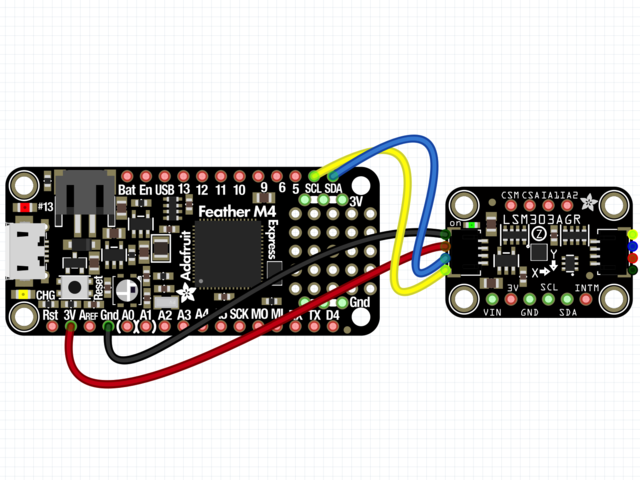
首先連接LSM303使用I2C連接完全按照Arduino的前幾頁中的說明連接到板上。以下是使用I2C將Feather M0連接到傳感器的示例:
 li》
li》
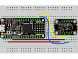
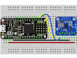
板3V 到傳感器VIN(紅線)
板GND 到傳感器GND (黑線)
板SCL 到傳感器SCL(黃線)
板SDA 到傳感器SDA(藍線)
Python計算機接線
因為有幾十個 您可以使用的Linux計算機/主板,我們將顯示Raspberry Pi的接線。對于其他平臺,請訪問Linux上的CircuitPython指南,以了解您的平臺是否受支持。
以下是與I2C相連的Raspberry Pi:
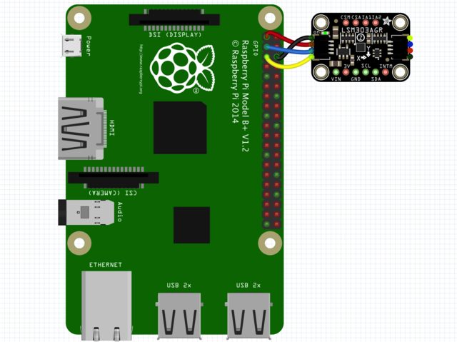


Pi 3V 到傳感器VIN(紅線)
Pi GND 到傳感器GND(黑線)
Pi SCL 到傳感器SCL(黃線)
Pi SDA 到傳感器SDA(藍線)
》
CircuitPython安裝LSM303庫
接下來,您需要安裝Adafruit CircuitPython LSM303加速度計和Adafruit CircuitPython LSM303AGR或Adafruit CircuitPython LSM303DLH magn etometer(取決于您擁有的LSM303)庫。
首先請確保您正在為板運行最新版本的Adafruit CircuitPython。
下一步,您需要安裝使用硬件所需的庫-請仔細按照以下步驟從Adafruit的CircuitPython庫捆綁包中查找和安裝這些庫。我們的簡介指南上有一個很棒的頁面,介紹如何為快速和非表達板安裝庫包。
請記住非表達板,例如,您需要從束中手動安裝必要的庫:
adafruit_lsm303agr_mag.mpy或adafruit_lsm303dlh_mag.mpy
adafruit_lsm303_accel.mpy
adafruit_bus_device
adafruit_register
在繼續(xù)之前,請確保您董事會的lib文件夾或根文件系統(tǒng)具有 adafruit_lsm303agr_mag .mpy或adafruit_lsm303dlh_mag.mpy, adafruit_lsm303_accel.mpy,adafruit_register,和 adafruit_bus_device 文件和文件夾
下一步連接到開發(fā)板的串行REPL,因此您位于CircuitPython的》》》 提示符下。
LSM303 Li的Python安裝braries
您需要安裝 Adafruit_Blinka 庫,該庫在Python中提供了CircuitPython支持。這可能還需要在您的平臺上啟用I2C并驗證您正在運行Python3。由于每個平臺都有所不同,并且Linux經(jīng)常更改,請訪問Linux上的CircuitPython指南以準備好您的計算機!
完成后,從命令行運行以下命令:
sudo pip3 install adafruit-circuitpython-lsm303-accel
然后為您的LSM303版本安裝磁力計庫。 :
LSM303AGR:
sudo pip3 install adafruit-circuitpython-lsm303agr-mag
LSM303DLH:
sudo pip3 install adafruit-circuitpython-lsm303dlh-mag
如果您的默認Python是版本3,則可能需要運行“ pip”。只要確保您不嘗試在Python 2.x上使用CircuitPython,就不支持它!
CircuitPython和Python用法
這些示例使用adafruit_lsm303agr_mag庫。如果您擁有l(wèi)sm303dlh,則必須更改代碼以使用adafruit_lsm303dlh_mag庫
為演示傳感器的用法,我們將對其進行初始化并讀取
運行以下代碼以導入必要的模塊,并初始化與傳感器的I2C連接:
》 LSM303AGR
下載:文件
復制代碼
import board
import busio
import adafruit_lsm303_accel
import adafruit_lsm303agr_mag
i2c = busio.I2C(board.SCL, board.SDA)
mag = adafruit_lsm303agr_mag.LSM303AGR_Mag(i2c)
accel = adafruit_lsm303_accel.LSM303_Accel(i2c) import board
import busio
import adafruit_lsm303_accel
import adafruit_lsm303agr_mag
i2c = busio.I2C(board.SCL, board.SDA)
mag = adafruit_lsm303agr_mag.LSM303AGR_Mag(i2c)
accel = adafruit_lsm303_accel.LSM303_Accel(i2c)

LSM303DLH
下載:文件
復制代碼
import board
import busio
import adafruit_lsm303_accel
import adafruit_lsm303dlh_mag
i2c = busio.I2C(board.SCL, board.SDA)
mag = adafruit_lsm303dlh_mag.LSM303DLH_Mag(i2c)
accel = adafruit_lsm303_accel.LSM303_Accel(i2c) import board
import busio
import adafruit_lsm303_accel
import adafruit_lsm303dlh_mag
i2c = busio.I2C(board.SCL, board.SDA)
mag = adafruit_lsm303dlh_mag.LSM303DLH_Mag(i2c)
accel = adafruit_lsm303_accel.LSM303_Accel(i2c)

現(xiàn)在,您可以使用以下屬性之一從傳感器讀取值:
加速度計
加速度-X,Y, Z加速度值,單位為米每秒每秒(m/s ^ 2)。
磁力計
磁性-微型特斯拉中X,Y,Z磁力計讀數(shù)的三元組。
下載:文件
復制代碼
print(“Acceleration (m/s^2): X=%0.3f Y=%0.3f Z=%0.3f”%accel.acceleration)
print(“Magnetometer (micro-Teslas)): X=%0.3f Y=%0.3f Z=%0.3f”%mag.magnetic) print(“Acceleration (m/s^2): X=%0.3f Y=%0.3f Z=%0.3f”%accel.acceleration)
print(“Magnetometer (micro-Teslas)): X=%0.3f Y=%0.3f Z=%0.3f”%mag.magnetic)

點擊檢測
LSM303的加速度計還可以檢測單次或兩次點擊!
set_tap 方法可用于設置要檢測的抽頭數(shù)(1或2),以及設置抽頭閾值。閾值越低,加速度計對檢測抽頭越敏感。您可能必須使用這個數(shù)字來找到適合您需求的值
在這里,我們還將使用 range 屬性將加速度計的測量范圍更改為 +/- 8G
下載:文件
復制代碼
accel.range = adafruit_lsm303_accel.Range.RANGE_8G
accel.set_tap(1, 30)
while True:
if accel.tapped:
print(“Tapped! ”) accel.range = adafruit_lsm303_accel.Range.RANGE_8G
accel.set_tap(1, 30)
while True:
if accel.tapped:
print(“Tapped! ”)
當您在REPL中鍵入上面的代碼并給傳感器一個良好的固定點擊時,您應該會看到類似于輸出如下。如果看不到“已點擊!” 消息,則可能需要調(diào)整閾值。

As您可以從上面看到,tapped屬性將在一個單擊事件的多個周期內(nèi)返回True。您必須在代碼中對此進行說明。不幸的是,這似乎只是傳感器的一個怪癖
這是將LSM303與CircuitPython一起使用的全部內(nèi)容。
下面是一個每秒讀取傳感器并打印其值的完整示例。將其另存為板上的 code.py 并打開REPL以查看輸出。
點擊檢測代碼
下載:Project Zip 或 tap_detection.py | 在Github上查看
復制代碼
import board
import busio
import adafruit_lsm303_accel
i2c = busio.I2C(board.SCL, board.SDA)
accel = adafruit_lsm303_accel.LSM303_Accel(i2c)
accel.range = adafruit_lsm303_accel.Range.RANGE_8G
accel.set_tap(1, 30)
while True:
if accel.tapped:
print(“Tapped! ”)
import board
import busio
import adafruit_lsm303_accel
i2c = busio.I2C(board.SCL, board.SDA)
accel = adafruit_lsm303_accel.LSM303_Accel(i2c)
accel.range = adafruit_lsm303_accel.Range.RANGE_8G
accel.set_tap(1, 30)
while True:
if accel.tapped:
print(“Tapped! ”)
LSM303AGR示例代碼
下載:Project Zip 或 lsm303agr_combined .py | 在Github上查看
復制代碼
from time import sleep
import board
import busio
import adafruit_lsm303_accel
import adafruit_lsm303agr_mag
i2c = busio.I2C(board.SCL, board.SDA)
mag = adafruit_lsm303agr_mag.LSM303AGR_Mag(i2c)
accel = adafruit_lsm303_accel.LSM303_Accel(i2c)
while True:
print(“Acceleration (m/s^2): X=%0.3f Y=%0.3f Z=%0.3f”%accel.acceleration)
print(“Magnetometer (micro-Teslas)): X=%0.3f Y=%0.3f Z=%0.3f”%mag.magnetic)
print(“”)
sleep(0.5)
LSM303DLH示例代碼
下載:Project Zip 或 lsm303dlh_combined.py | 在Github上查看
復制代碼
from time import sleep
import board
import busio
import adafruit_lsm303_accel
import adafruit_lsm303dlh_mag
i2c = busio.I2C(board.SCL, board.SDA)
mag = adafruit_lsm303dlh_mag.LSM303DLH_Mag(i2c)
accel = adafruit_lsm303_accel.LSM303_Accel(i2c)
while True:
print(“Acceleration (m/s^2): X=%0.3f Y=%0.3f Z=%0.3f”%accel.acceleration)
print(“Magnetometer (micro-Teslas)): X=%0.3f Y=%0.3f Z=%0.3f”%mag.magnetic)
print(“”)
sleep(0.5)
Adafruit_CircuitPython_LSM303庫已存檔
用于較早的LSM303DLH突破的Adafruit_CircuitPython_LSM303庫已存檔,并已由上面使用的Adafruit_CircuitPython_LSM303_Accel和Adafruit_CircuitPython_LSM303DLH_Mag庫替換。我們建議您切換到較新的庫,因為不支持舊的庫或添加了功能。
如果您仍然希望使用舊的庫,則可以單擊下面的按鈕轉(zhuǎn)到存儲庫或以ZIP格式下載。
已存檔的Adafruit_CircuitPython_LSM303存儲庫
下載Adafruit_CircuitPython_LSM303
校準
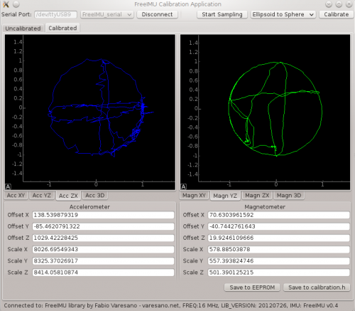
(Fabio Varesano的校準GUI圖像)
LSM303芯片在出廠時已校準到足以滿足多種目的的精確度。但是對于IMU等超臨界應用程序,您可能需要進一步校準設備。
最終校準:
要進行超高精度加速度計校準,您將需要查看已故的Fabio Varesano提供的FreeIMU磁力計和加速度計GUI。上面的圖像(來自Fabio網(wǎng)站)顯示了傳感器讀數(shù)的圖形表示以及根據(jù)原始數(shù)據(jù)計算出的校準偏差。
此全面的校準套件旨在在PC上運行。它太大了,無法在像Arduino這樣的微控制器上運行,但是它產(chǎn)生的校準偏差可以并入您的Arduino草圖中,以提高準確性。
簡化的校準:
可以在Arduino上完成仍然產(chǎn)生良好結(jié)果的更簡單方法。該方法使用一個簡單的草圖記錄所有3軸上的最小和最大讀數(shù)。運行草圖時,在所有三個軸上緩慢旋轉(zhuǎn)LSM303模塊多次。目的是記錄每個軸的絕對最小值和最大值,因此旋轉(zhuǎn)得越多,捕獲絕對峰值的可能性就越大。
請確保將傳感器緩慢繞其中心旋轉(zhuǎn),以使加速度計讀數(shù)將僅表示由于重力引起的加速度,而不表示由于運動引起的傳感器線性加速度。稍后,草圖輸出將穩(wěn)定。顯示的值將是每個軸的最小和最大范圍,可用于重新縮放傳感器的輸出。
通過校準草圖獲得的值可用于執(zhí)行在三個軸上分別進行兩點校準:兩點校準
校準草圖:
LSM303AGR
下載:Project Zip 或 calibration.ino | 在Github上查看
復制代碼
#include
#include
#include
Adafruit_LSM303AGR_Mag_Unified mag = Adafruit_LSM303AGR_Mag_Unified(12345);
float MagMinX, MagMaxX;
float MagMinY, MagMaxY;
float MagMinZ, MagMaxZ;
long lastDisplayTime;
void setup(void)
{
Serial.begin(115200);
Serial.println(“LSM303 Calibration”); Serial.println(“”);
/* Initialise the magnetometer */
if(!mag.begin())
{
/* There was a problem detecting the LSM303 。.. check your connections */
Serial.println(“Ooops, no LSM303 detected 。.. Check your wiring!”);
while(1);
}
lastDisplayTime = millis();
}
void loop(void)
{
/* Get a new sensor event */
sensors_event_t magEvent;
mag.getEvent(&magEvent);
if (magEvent.magnetic.x 《 MagMinX) MagMinX = magEvent.magnetic.x;
if (magEvent.magnetic.x 》 MagMaxX) MagMaxX = magEvent.magnetic.x;
if (magEvent.magnetic.y 《 MagMinY) MagMinY = magEvent.magnetic.y;
if (magEvent.magnetic.y 》 MagMaxY) MagMaxY = magEvent.magnetic.y;
if (magEvent.magnetic.z 《 MagMinZ) MagMinZ = magEvent.magnetic.z;
if (magEvent.magnetic.z 》 MagMaxZ) MagMaxZ = magEvent.magnetic.z;
if ((millis() - lastDisplayTime) 》 1000) // display once/second
{
Serial.print(“Mag Minimums: ”); Serial.print(MagMinX); Serial.print(“ ”);Serial.print(MagMinY); Serial.print(“ ”); Serial.print(MagMinZ); Serial.println();
Serial.print(“Mag Maximums: ”); Serial.print(MagMaxX); Serial.print(“ ”);Serial.print(MagMaxY); Serial.print(“ ”); Serial.print(MagMaxZ); Serial.println(); Serial.println();
lastDisplayTime = millis();
}
}
#include
#include
#include
Adafruit_LSM303AGR_Mag_Unified mag = Adafruit_LSM303AGR_Mag_Unified(12345);
float MagMinX, MagMaxX;
float MagMinY, MagMaxY;
float MagMinZ, MagMaxZ;
long lastDisplayTime;
void setup(void)
{
Serial.begin(115200);
Serial.println(“LSM303 Calibration”); Serial.println(“”);
/* Initialise the magnetometer */
if(!mag.begin())
{
/* There was a problem detecting the LSM303 。.. check your connections */
Serial.println(“Ooops, no LSM303 detected 。.. Check your wiring!”);
while(1);
}
lastDisplayTime = millis();
}
void loop(void)
{
/* Get a new sensor event */
sensors_event_t magEvent;
mag.getEvent(&magEvent);
if (magEvent.magnetic.x 《 MagMinX) MagMinX = magEvent.magnetic.x;
if (magEvent.magnetic.x 》 MagMaxX) MagMaxX = magEvent.magnetic.x;
if (magEvent.magnetic.y 《 MagMinY) MagMinY = magEvent.magnetic.y;
if (magEvent.magnetic.y 》 MagMaxY) MagMaxY = magEvent.magnetic.y;
if (magEvent.magnetic.z 《 MagMinZ) MagMinZ = magEvent.magnetic.z;
if (magEvent.magnetic.z 》 MagMaxZ) MagMaxZ = magEvent.magnetic.z;
if ((millis() - lastDisplayTime) 》 1000) // display once/second
{
Serial.print(“Mag Minimums: ”); Serial.print(MagMinX); Serial.print(“ ”);Serial.print(MagMinY); Serial.print(“ ”); Serial.print(MagMinZ); Serial.println();
Serial.print(“Mag Maximums: ”); Serial.print(MagMaxX); Serial.print(“ ”);Serial.print(MagMaxY); Serial.print(“ ”); Serial.print(MagMaxZ); Serial.println(); Serial.println();
lastDisplayTime = millis();
}
}
LSM303/LSM303DLH
下載:項目Zip 或 calibration.ino | 在Github上查看
復制代碼
#include
#include
//#include
#include
Adafruit_LSM303DLH_Mag_Unified mag = Adafruit_LSM303DLH_Mag_Unified(12345);
float MagMinX, MagMaxX;
float MagMinY, MagMaxY;
float MagMinZ, MagMaxZ;
long lastDisplayTime;
void setup(void) {
Serial.begin(115200);
Serial.println(“LSM303 Calibration”);
Serial.println(“”);
/* Initialise the magnetometer */
if (!mag.begin()) {
/* There was a problem detecting the LSM303 。.. check your connections */
Serial.println(“Ooops, no LSM303 detected 。.. Check your wiring!”);
while (1)
;
}
lastDisplayTime = millis();
}
void loop(void) {
/* Get a new sensor event */
sensors_event_t magEvent;
mag.getEvent(&magEvent);
if (magEvent.magnetic.x 《 MagMinX)
MagMinX = magEvent.magnetic.x;
if (magEvent.magnetic.x 》 MagMaxX)
MagMaxX = magEvent.magnetic.x;
if (magEvent.magnetic.y 《 MagMinY)
MagMinY = magEvent.magnetic.y;
if (magEvent.magnetic.y 》 MagMaxY)
MagMaxY = magEvent.magnetic.y;
if (magEvent.magnetic.z 《 MagMinZ)
MagMinZ = magEvent.magnetic.z;
if (magEvent.magnetic.z 》 MagMaxZ)
MagMaxZ = magEvent.magnetic.z;
if ((millis() - lastDisplayTime) 》 1000) // display once/second
{
Serial.print(“Mag Minimums: ”);
Serial.print(MagMinX);
Serial.print(“ ”);
Serial.print(MagMinY);
Serial.print(“ ”);
Serial.print(MagMinZ);
Serial.println();
Serial.print(“Mag Maximums: ”);
Serial.print(MagMaxX);
Serial.print(“ ”);
Serial.print(MagMaxY);
Serial.print(“ ”);
Serial.print(MagMaxZ);
Serial.println();
Serial.println();
lastDisplayTime = millis();
}
} #include
#include
//#include
#include
Adafruit_LSM303DLH_Mag_Unified mag = Adafruit_LSM303DLH_Mag_Unified(12345);
float MagMinX, MagMaxX;
float MagMinY, MagMaxY;
float MagMinZ, MagMaxZ;
long lastDisplayTime;
void setup(void) {
Serial.begin(115200);
Serial.println(“LSM303 Calibration”);
Serial.println(“”);
/* Initialise the magnetometer */
if (!mag.begin()) {
/* There was a problem detecting the LSM303 。.. check your connections */
Serial.println(“Ooops, no LSM303 detected 。.. Check your wiring!”);
while (1)
;
}
lastDisplayTime = millis();
}
void loop(void) {
/* Get a new sensor event */
sensors_event_t magEvent;
mag.getEvent(&magEvent);
if (magEvent.magnetic.x 《 MagMinX)
MagMinX = magEvent.magnetic.x;
if (magEvent.magnetic.x 》 MagMaxX)
MagMaxX = magEvent.magnetic.x;
if (magEvent.magnetic.y 《 MagMinY)
MagMinY = magEvent.magnetic.y;
if (magEvent.magnetic.y 》 MagMaxY)
MagMaxY = magEvent.magnetic.y;
if (magEvent.magnetic.z 《 MagMinZ)
MagMinZ = magEvent.magnetic.z;
if (magEvent.magnetic.z 》 MagMaxZ)
MagMaxZ = magEvent.magnetic.z;
if ((millis() - lastDisplayTime) 》 1000) // display once/second
{
Serial.print(“Mag Minimums: ”);
Serial.print(MagMinX);
Serial.print(“ ”);
Serial.print(MagMinY);
Serial.print(“ ”);
Serial.print(MagMinZ);
Serial.println();
Serial.print(“Mag Maximums: ”);
Serial.print(MagMaxX);
Serial.print(“ ”);
Serial.print(MagMaxY);
Serial.print(“ ”);
Serial.print(MagMaxZ);
Serial.println();
Serial.println();
lastDisplayTime = millis();
}
}
制作曲目!
現(xiàn)在讓我們使用LSM303模塊進行一些簡單的導航!
此頁面上的圖像顯示較舊的LSM303DLH。您也可以使用更新的LSM303AGR,但需要參考“引腳分配”頁面來確定要使用的引腳
一天,制作曲目
在Prax草原上,
來一個北向Zax
和一個南向Zax。
此Zax-O-Meter是北部或南部Zax的理想導航工具。該項目演示了如何使用LSM303磁力計輸出來實現(xiàn)簡單的導航系統(tǒng)。無論您以哪種方式旋轉(zhuǎn),指針都將始終旋轉(zhuǎn)到所需的行進方向。
永不退縮!這是我的規(guī)則。
從不退縮!
向西不遠一英寸!
向東不一英寸!
Zax-O-Meter使用計算出的指南針航向作為連續(xù)旋轉(zhuǎn)的反饋伺服。當指南針航向為零度(正北)時,伺服器停止旋轉(zhuǎn)。與該值的任何偏差都會導致伺服器朝相反的方向旋轉(zhuǎn)以進行補償。負反饋的基本原理可用于構(gòu)建自主機器人的導航系統(tǒng)。
材料:要構(gòu)建Zax-O-Meter,您將需要:
Adafruit LSM303接線板
Arduino Uno
Arduino機箱
連續(xù)旋轉(zhuǎn)伺服系統(tǒng)
跳線
卡片紙
紙板或泡沫芯
校準伺服器:為使Zax-O-Meter準確運行,您首先需要找到連續(xù)旋轉(zhuǎn)伺服器的“中性”點。這是導致最小旋轉(zhuǎn)的伺服輸出值。該值通常約為90,但在伺服之間有所不同。運行此草圖并修改值,直到獲得最小旋轉(zhuǎn)。那就是您應該在Zax-O-Meter草圖中為ServoNeutral使用的值。
下載:文件
復制代碼
#include
Servo servo;
void setup()
{
servo.attach(9); // attaches the servo on pin 9 to the servo object
servo.write(90); // change this value to achieve minimum rotation!
}
void loop()
{
} #include
Servo servo;
void setup()
{
servo.attach(9); // attaches the servo on pin 9 to the servo object
servo.write(90); // change this value to achieve minimum rotation!
}
void loop()
{
}
安裝伺服器,標記并加寬外殼中的開口以適合伺服器。將伺服器的轉(zhuǎn)子對準外殼的中心。向下按直到法蘭與表面齊平,舵機應卡入到位并牢固固定。
安裝Uno并將其連接使用隨附的螺釘將Uno安裝在機箱中。如下連接伺服和傳感器:
伺服:
黑色-》 Gnd
紅色-》 5v
白色-》數(shù)字引腳9
LSM303:
Gnd-》 Gnd
Vin-》 3.3v
SDA-》模擬4
SCL-》模擬5
然后將傳感器導線穿過伺服器旁邊的開口并關閉外殼。
添加指針從一些堅硬的硬紙板或泡沫芯,并用一些雙面泡沫膠帶將其粘貼到伺服喇叭上。
用一些雙面泡沫膠帶將傳感器固定在箭頭的下方。將傳感器放置在盡可能遠離伺服主體的位置,以避免電動機產(chǎn)生電磁干擾。
添加Zaxen!查找您最喜歡的Zax的圖片。使用“畫圖”或其他圖像編輯工具制作一對鏡像圖像。
將圖像打印在一些較重的卡片紙上,然后將其折疊以制作雙面圖像。
將其切出并安裝在其頂部。帶有雙面膠帶的指示箭頭。
代碼:加載以下代碼。不要忘記在“伺服校準”步驟中將“ ServoNeutral”更改為中性值。
示例代碼適用于北向Zax,目標標題為0。如果您是南向說服的Zax ,targetHeading為180將使您一直處在向南的位置。對于那些背叛的人,請在0-360度之間選擇任何targetHeading設置,然后開始在您選擇的標題中進行跟蹤!
下載:文件
復制代碼
// **********************************************
// Zax-O-Meter Sketch
// for the Adafruit LSM303 Magnetometer Breakout
//
// Written by Bill Earl for Adafruit Industries
//
// **********************************************
#include
#include
#include
#include
/* Assign a unique ID to this sensor at the same time */
Adafruit_LSM303_Mag_Unified mag = Adafruit_LSM303_Mag_Unified(12345);
// This is our continuous rotation servo
Servo servo;
// Pi for calculations - not the raspberry type
const float Pi = 3.14159;
// This is the value that gives you minimal rotation on
// a continuous rotation servo. It is usually about 90.
// adjust this value to give minimal rotation for your servo
const float ServoNeutral = 97;
// This is the desired direction of travel
// expressed as a 0-360 degree compass heading
// 0.0 = North
// 90.0 = East
// 180.0 = South
// 270 = West
const float targetHeading = 0.0;
void setup(void)
{
Serial.begin(9600);
Serial.println(“Magnetometer Test”); Serial.println(“”);
/* Initialise the sensor */
if(!mag.begin())
{
/* There was a problem detecting the LSM303 。.. check your connections */
Serial.println(“Ooops, no LSM303 detected 。.. Check your wiring!”);
while(1);
}
servo.attach(9); // Attach servo to pin 9
}
void loop(void)
{
/* Get a new sensor event */
sensors_event_t event;
mag.getEvent(&event);
// Calculate the angle of the vector y,x
float heading = (atan2(event.magnetic.y,event.magnetic.x) * 180) / Pi;
// Normalize to 0-360
if (heading 《 0)
{
heading = 360 + heading;
}
// Calculate the error between tha measured heading and the target heading.
float error = heading - targetHeading;
if (error 》 180)
{
error = error - 360; // for angles 》 180, correct in the opposite direction.
}
// A non-zero difference between the heading and the
// targetHeading will bias the servoNeutral value and
// cause the servo to rotate back toward the targetHeading.
// The divisor is to reduce the reaction speed and avoid oscillations
servo.write(ServoNeutral + error / 4 );
delay(40);
} // **********************************************
// Zax-O-Meter Sketch
// for the Adafruit LSM303 Magnetometer Breakout
//
// Written by Bill Earl for Adafruit Industries
//
// **********************************************
#include
#include
#include
#include
/* Assign a unique ID to this sensor at the same time */
Adafruit_LSM303_Mag_Unified mag = Adafruit_LSM303_Mag_Unified(12345);
// This is our continuous rotation servo
Servo servo;
// Pi for calculations - not the raspberry type
const float Pi = 3.14159;
// This is the value that gives you minimal rotation on
// a continuous rotation servo. It is usually about 90.
// adjust this value to give minimal rotation for your servo
const float ServoNeutral = 97;
// This is the desired direction of travel
// expressed as a 0-360 degree compass heading
// 0.0 = North
// 90.0 = East
// 180.0 = South
// 270 = West
const float targetHeading = 0.0;
void setup(void)
{
Serial.begin(9600);
Serial.println(“Magnetometer Test”); Serial.println(“”);
/* Initialise the sensor */
if(!mag.begin())
{
/* There was a problem detecting the LSM303 。.. check your connections */
Serial.println(“Ooops, no LSM303 detected 。.. Check your wiring!”);
while(1);
}
servo.attach(9); // Attach servo to pin 9
}
void loop(void)
{
/* Get a new sensor event */
sensors_event_t event;
mag.getEvent(&event);
// Calculate the angle of the vector y,x
float heading = (atan2(event.magnetic.y,event.magnetic.x) * 180) / Pi;
// Normalize to 0-360
if (heading 《 0)
{
heading = 360 + heading;
}
// Calculate the error between tha measured heading and the target heading.
float error = heading - targetHeading;
if (error 》 180)
{
error = error - 360; // for angles 》 180, correct in the opposite direction.
}
// A non-zero difference between the heading and the
// targetHeading will bias the servoNeutral value and
// cause the servo to rotate back toward the targetHeading.
// The divisor is to reduce the reaction speed and avoid oscillations
servo.write(ServoNeutral + error / 4 );
delay(40);
}
下載和鏈接
文件 strong》
LSM303AGR
LSM303AGR數(shù)據(jù)表
PCB文件(Eagle格式)
Adafruit Fritzing庫中的裝飾對象
LSM303DLHC
LSM303DLHC數(shù)據(jù)表
PCB文件(鷹格式)
Adafruit中的Fritzing對象Fritzing庫
LSM0303AGR示意圖&Fab Print

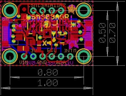
LSM303DLHC示意圖和構(gòu)造打印


責任編輯:wv
-
Arduino
+關注
關注
188文章
6472瀏覽量
187360 -
LSM303D
+關注
關注
0文章
2瀏覽量
9826
發(fā)布評論請先 登錄
相關推薦
將ADS8402/ADS8412連接到TMS320C6713 DSP

將ADS8320/ADS8325連接到TMS320C6711 DSP

將ADS8401/ADS8411連接到TMS320C6713 DSP

將ADS8383連接到TMS320C6711 DSP

將ADS7881連接到TMS320C6713 DSP

如何將LVDS/OLDI橋接到HDMI/DVI

將C2000連接到AFE03x:B-FSK示例

使用ESP8266將arduino連接到thinkspeak云,無法將其連接到任何網(wǎng)頁,為什么?
能將ESP8266連接到arduino UNO上,使用mesh組網(wǎng)嗎?
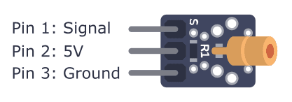
如何將KY-008連接到Arduino
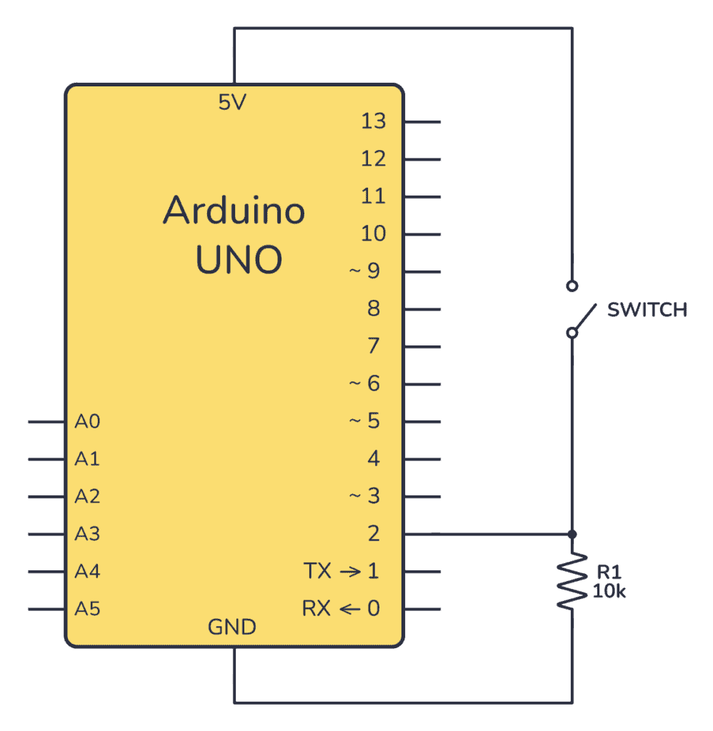
如何將按鈕連接到Arduino板
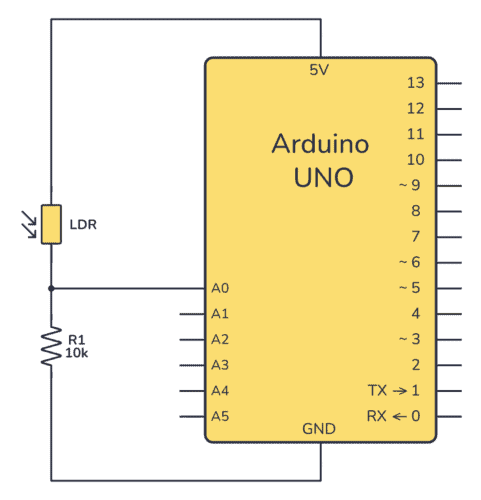
如何將光敏電阻連接到Arduino板并讀取電壓
如何將HC-SR04連接到Arduino并編寫一個簡單的程序來測量距離
如何將增量旋轉(zhuǎn)編碼器與Arduino連接


 如何將LSM303連接到Arduino


評論