我拿到的開發板實際板載的 MCU 是 GD32F310G8,QFN28pin 封裝,基于 ARM CORTEX M4 內核,主頻 72MHz, 芯片內置 64KB flash,8KB SRAM, 兩路 I2C 外設。
整體概述
首先感謝極術社區給我試用GD32開發板的機會,讓我體驗一下近幾年國產MCU開發體驗。該芯片是基于arm cortex-M4內核,主頻72Mhz,flash 64k,ram 8k,以及豐富的外設。
本次試用是一個讀取三軸加速度計的實驗,主要使用的是硬件iic。
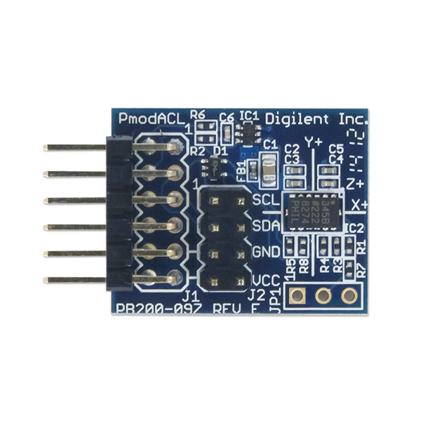
硬件連接
傳感器介紹
SC7A20 是一款高精度 12bit 數字三軸加速度傳感器芯片,內置功能 更豐富,功耗更低,體積更小,測量更精確。
芯片通過 IC2/SPI 接口與 MCU 通信,加速度測量數據以中斷方式或 查詢方式獲取。INT1和INT2中斷管腳提供多種內部自動檢測的中斷信號, 適應多種運動檢測場合,中斷源包括 6D/4D 方向檢測中斷信號、自由落體 檢測中斷信號、睡眠和喚醒檢測中斷信號、單擊和雙擊檢測中斷信號。
芯片內置高精度校準模塊,對傳感器的失調誤差和增益誤差進行精確補償。 ±2G、±4G、±8G 和±16G 四種可調整的全量程測量范圍,靈活測量外 部加速度,輸出數據率 1HZ 和 400HZ 間可選。
軟件功能
該軟件主要使用了GD32開發板的硬件iic,外部中斷以及串口,這三部分功能,串口的配置在其他文章的當中已經有敘述,本文只主要介紹iic和外部中斷的使用.
硬件iic
初始化gpio

配置硬件iic

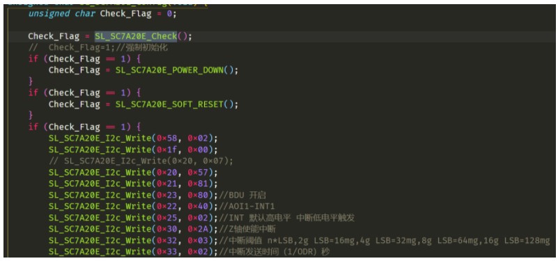
根據廠商提供的庫函數(具體參考gd32f3x0_i2c.c文件),我們可以很容易的初始化iic。剩下的就是對傳感器進行配置了,該傳感器需要配置寄存器較多,廠商直接提供了一份demo程序,只需要適配讀取寫入的接口就可以很快的使用了。

我需要做的就是把iic的讀取和寫入進行適配適配函數如下:
void I2C_LeaderWrite(uint16_t followerAddress, , uint8_t targetAddress, uint8_t *txBuff,
                     uint8_t numBytes) {
    /* wait until I2C bus is idle */
    while (i2c_flag_get(I2C0, I2C_FLAG_I2CBSY))
        ;
    /* send a start condition to I2C bus */
    i2c_start_on_bus(I2C0);
    /* wait until SBSEND bit is set */
    while (!i2c_flag_get(I2C0, I2C_FLAG_SBSEND))
        ;
    /* send slave address to I2C bus */
    i2c_master_addressing(I2C0, followerAddress, I2C_TRANSMITTER);
    /* wait until ADDSEND bit is set */
    while (!i2c_flag_get(I2C0, I2C_FLAG_ADDSEND))
        ;
    /* clear ADDSEND bit */
    i2c_flag_clear(I2C0, I2C_FLAG_ADDSEND);
    /* wait until the transmit data buffer is empty */
    while (!i2c_flag_get(I2C0, I2C_FLAG_TBE))
        ;

    for (i = 0; i < numBytes; i++) {
        /* data transmission */
        i2c_data_transmit(I2C0, txBuff[i]);
        /* wait until the TBE bit is set */
        while (!i2c_flag_get(I2C0, I2C_FLAG_TBE))
            ;
    }
    /* send a stop condition to I2C bus */
    i2c_stop_on_bus(I2C0);
    /* wait until stop condition generate */
    while (I2C_CTL0(I2C0) & 0x0200)
        ;
}
void I2C_LeaderRead(uint16_t followerAddress, uint8_t targetAddress, uint8_t *rxBuff,
                    uint8_t numBytes) {
    /* wait until I2C bus is idle */
    while (i2c_flag_get(I2C0, I2C_FLAG_I2CBSY))
        ;

    /* send a start condition to I2C bus */
    i2c_start_on_bus(I2C0);

    /* wait until SBSEND bit is set */
    while (!i2c_flag_get(I2C0, I2C_FLAG_SBSEND))
        ;

    /* send slave address to I2C bus */
    i2c_master_addressing(I2C0, followerAddress, I2C_TRANSMITTER);

    /* wait until ADDSEND bit is set */
    while (!i2c_flag_get(I2C0, I2C_FLAG_ADDSEND))
        ;

    /* clear the ADDSEND bit */
    i2c_flag_clear(I2C0, I2C_FLAG_ADDSEND);

    /* wait until the transmit data buffer is empty */
    while (SET != i2c_flag_get(I2C0, I2C_FLAG_TBE))
        ;

    /* enable I2C0*/
    i2c_enable(I2C0);

    /* send the EEPROM's internal address to write to */
    i2c_data_transmit(I2C0, targetAddress);

    /* wait until BTC bit is set */
    while (!i2c_flag_get(I2C0, I2C_FLAG_BTC))
        ;

    /* send a start condition to I2C bus */
    i2c_start_on_bus(I2C0);

    /* wait until SBSEND bit is set */
    while (!i2c_flag_get(I2C0, I2C_FLAG_SBSEND))
        ;

    /* send slave address to I2C bus */
    i2c_master_addressing(I2C0, followerAddress, I2C_RECEIVER);

    /* wait until ADDSEND bit is set */
    while (!i2c_flag_get(I2C0, I2C_FLAG_ADDSEND))
        ;

    /* clear the ADDSEND bit */
    i2c_flag_clear(I2C0, I2C_FLAG_ADDSEND);

    /* while there is data to be read */
    for (int i = 0; i < numBytes; i++) {
        /* code */

        /* read a data from I2C_DATA */
        rxBuff[i++] = i2c_data_receive(I2C0);
        /* send a stop condition */
        i2c_stop_on_bus(I2C0);
    }

    /* wait until the stop condition is finished */
    while (I2C_CTL0(I2C0) & 0x0200)
        ;

    /* enable acknowledge */
    i2c_ack_config(I2C0, I2C_ACK_ENABLE);

    i2c_ackpos_config(I2C0, I2C_ACKPOS_CURRENT);
}
然后把這兩個函數適配:

然后對傳感器進行設置

外部中斷
使用外部中斷可以使用用于喚醒mcu,這對設計低功耗的產品很有意義,當傳感器超過設定的閾值的時候,那么就會產生一個中斷來通知mcu,需要進一步的處理數據,外部中斷的配置如下所示:
void exit_wakeup_interrupt_config(void)
{
     /* configure the priority group */
    nvic_priority_group_set(NVIC_PRIGROUP_PRE2_SUB2);

    /* enable the key wakeup clock */
    rcu_periph_clock_enable(RCU_GPIOA);
    rcu_periph_clock_enable(RCU_CFGCMP);

    /* configure button pin as input */
    gpio_mode_set(GPIOA, GPIO_MODE_INPUT, GPIO_PUPD_NONE, GPIO_PIN_0);

    /* enable and set key wakeup EXTI interrupt to the higher priority */
    nvic_irq_enable(EXTI0_1_IRQn, 2U, 0U);

    /* connect key wakeup EXTI line to key GPIO pin */
    syscfg_exti_line_config(EXTI_SOURCE_GPIOA, EXTI_SOURCE_PIN0);

    /* configure key wakeup EXTI line */
    exti_init(EXTI_0, EXTI_INTERRUPT, EXTI_TRIG_FALLING);
    exti_interrupt_flag_clear(EXTI_0);
}
數據處理
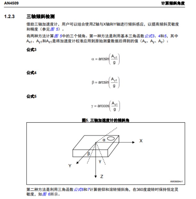
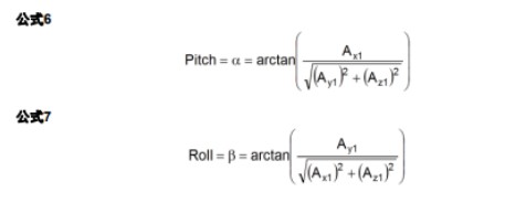
由于我們使用的是三軸傳感器,對于姿態位置的計算并不是很精確,因此,此處只用簡單角度計算,傾角的計算原理如下


計算代碼如下:
#define DEG_TO_RAD(x) ((x) * 0.01745329252)
#define RAD_TO_DEG(x) ((x) * 57.2957795131)
void angle_calculation() {
    double pitch, roll, paw;
    pitch = atan(xyz_mg[X] / sqrt(pow(xyz_mg[Y], 2) + pow(xyz_mg[Z], 2)));
    roll = atan(xyz_mg[Y] / sqrt(pow(xyz_mg[X], 2) + pow(xyz_mg[Z], 2)));
    paw = atan(sqrt(pow(xyz_mg[X], 2) + pow(xyz_mg[Y], 2)) / xyz_mg[Z]);

    printf("[RAD]pitch:%.2f | roll:%.2f | paw:%.2f rn", pitch, roll, paw);
    printf("[DEG]pitch:%.2f° | roll:%.2f° | paw:%.2f° rn", RAD_TO_DEG(pitch), RAD_TO_DEG(roll),
           RAD_TO_DEG(paw));
}
審核編輯:劉清
-
mcu
+關注
關注
146文章
17199瀏覽量
351922 -
三軸加速度計
+關注
關注
1文章
29瀏覽量
13368 -
SRAM控制器
+關注
關注
0文章
11瀏覽量
5908 -
GD32F3
+關注
關注
0文章
11瀏覽量
3857
發布評論請先 登錄
相關推薦


 在GD32F310G-START開發板上讀取三軸加速度計


評論