Problem 151-review2015_count1k
題目說明
構建一個從 0 到 999(含)計數的計數器,周期為 1000 個周期。復位輸入是同步的,應該將計數器復位為 0。

模塊端口聲明
moduletop_module(
inputclk,
inputreset,
output[9:0]q);
題目解析
moduletop_module(
inputlogicclk,
inputlogicreset,
outputlogic[9:0]q);


always_ff@(posedgeclk)begin
if(reset)begin
q<=?10'd0?;
????end
????else?if?(q?==?10'd999)?begin
????????q?<=?10'd0?;
????end
????else?begin
????????q?<=?q?+?10'd1?;
????end
????
end


endmodule

點擊Submit,等待一會就能看到下圖結果:
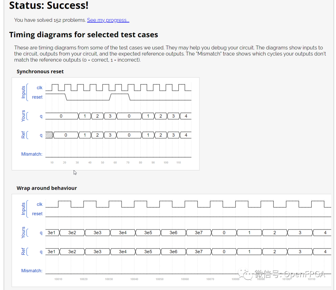
注意圖中的Ref是參考波形,Yours是你的代碼生成的波形,網站會對比這兩個波形,一旦這兩者不匹配,仿真結果會變紅。
這一題就結束了。
Problem 152-review2015_shiftcount
題目說明
接下來的五道題目,每題構建一個小型的電路,最終組裝成為一個復雜的計數器電路。
本題設計一個 4bit 位寬的移位寄存器,并具有計數器功能,可向下計數(即計數值遞減)。
當移位使能 shift_ena 信號有效時,數據 data 移入移位寄存器,向高位移動(most-significant-bit),即左移。
當計數使能 count_ena 信號有效時,寄存器中現有的數值遞減,向下計數。
由于系統不會同時使用移位以及計數功能,因此不需要考慮兩者使能信號皆有效的情況。

模塊端口聲明
moduletop_module(
inputclk,
inputshift_ena,
inputcount_ena,
inputdata,
output[3:0]q);
題目解析
moduletop_module(
inputlogicclk,
inputlogicshift_ena,
inputlogiccount_ena,
inputlogicdata,
outputlogic[3:0]q);

always_ff@(posedgeclk)begin
case(1'b1)
shift_ena:begin
q<=?{q[2:0]?,?data}?;?
????????end?
????????count_ena:?begin
????????????q?<=?q?-?4'd1?;
????????end
????????default:?begin
????????????q?<=?q?;
????????end?
????endcase
end

endmodule
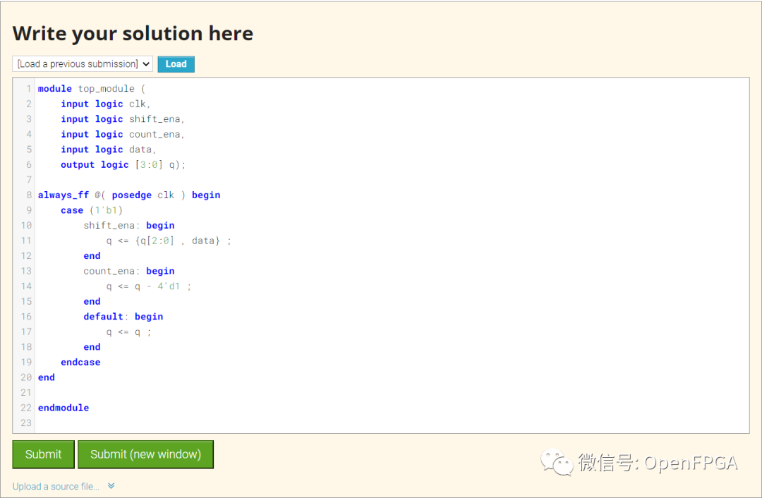
點擊Submit,等待一會就能看到下圖結果:
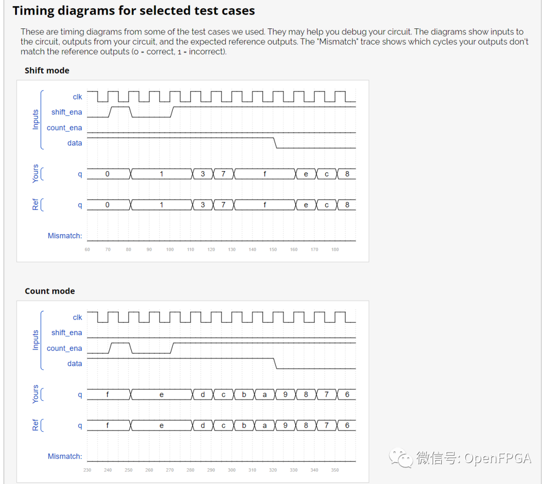
注意圖中的Ref是參考波形,Yours是你的代碼生成的波形,網站會對比這兩個波形,一旦這兩者不匹配,仿真結果會變紅。
這一題就結束了。
Problem 153-review2015_fsmseq
題目說明
接下來的五道題目,每題構建一個小型的電路,最終組裝成為一個復雜的計數器電路。
構建一個在輸入比特流中搜索序列 1101 的有限狀態機。當找到序列時,應該將start_shifting設置為 1,直到復位。卡在最終狀態旨在模擬在尚未實現的更大 FSM 中進入其他狀態。我們將在接下來的幾個練習中擴展這個 FSM。

模塊端口聲明
moduletop_module(
inputclk,
inputreset,//Synchronousreset
inputdata,
outputstart_shifting);
題目解析
檢查一個序列檢測狀態機是否完備,一個簡單的方法是觀察所有狀態,是否均包括輸入分別為 0/1 的情況下的跳轉,比如 state[IDLE ] && ~data 和 state[IDLE ] && data 是否均存在于狀態跳轉條件中。
moduletop_module(
inputlogicclk,
inputlogicreset,//Synchronousreset
inputlogicdata,
outputlogicstart_shifting
);

//definestate

typedefenumlogic[2:0]{idle=3'd1,S0=3'd2,
S1=3'd3,S2=3'd4,S3=3'd5
}state_def;

state_defcur_state,next_state;


//describestatetransitionusecombinationallogic

always_combbegin
case(cur_state)
idle:begin
next_state=data?S0:idle;
end

S0:begin
next_state=data?S1:idle;
end

S1:begin
next_state=data?S1:S2;
end

S2:begin
next_state=data?S3:idle;
end

S3:begin
next_state=S3;
end
default:begin
next_state=idle;
end
endcase
end


//describestatesequencerusesequentiallogic

always_ff@(posedgeclk)begin
if(reset)begin
cur_state<=?idle?;
????end
????else?begin
????????cur_state?<=?next_state?;
????end????
end

//describe?output?decoder?use?combinational?logic

assign?start_shifting?=?(cur_state?==?S3)?;

endmodule
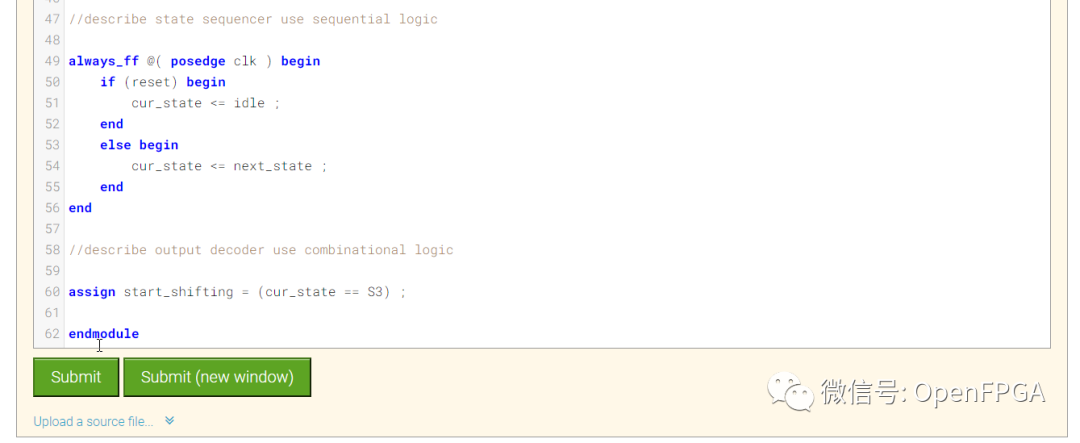
點擊Submit,等待一會就能看到下圖結果:
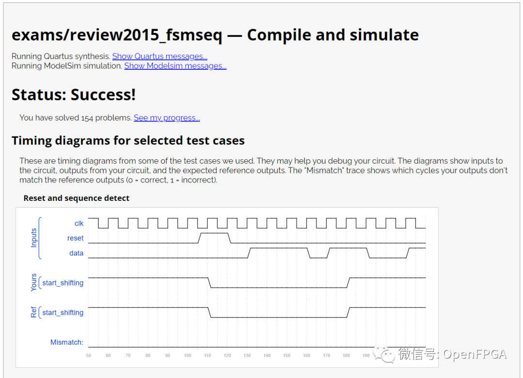
注意圖中的Ref是參考波形,Yours是你的代碼生成的波形,網站會對比這兩個波形,一旦這兩者不匹配,仿真結果會變紅。
這一題就結束了。
Problem 154-review2015_fsmshift
題目說明
接下來的五道題目,每題構建一個小型的電路,最終組裝成為一個復雜的計數器電路。
作為用于控制移位寄存器的 FSM 的一部分,我們希望能夠在檢測到正確的位模式時啟用移位寄存器正好 4 個時鐘周期。我們在Exams/review2015_fsmseq中處理序列檢測,因此 FSM 的這一部分僅處理啟用移位寄存器 4 個周期。
每當 FSM 復位時,將shift_ena斷言4 個周期,然后永遠為 0(直到復位)。
 圖片來自HDLBits
模塊端口聲明
moduletop_module(
inputclk,
inputreset,//Synchronousreset
outputshift_ena);
題目解析
題目要求 reset 信號移除后,立即 輸出使能信號,因此需要組合邏輯輸出。
moduletop_module(
inputlogicclk,
inputlogicreset,//Synchronousreset
outputlogicshift_ena);
//definestate
typedefenumlogic{S0=1'd0,S1=1'd1}state_def;
state_defcur_state,next_state;
//describestatesequencerusesequentiallogic
always_ff@(posedgeclk)begin
if(reset)begin
cur_state<=?S0?;
????end
????else?begin
????????cur_state?<=?next_state?;
????end
end
//describe?state?transition?use?combinational?logic
always_comb?begin?
????case?(cur_state)
????????S0:?begin
????????????next_state?=?reset???S0?:?S1?;
????????end
????????S1:?begin
????????????next_state?=?reset???S0?:?S1?;
????????end
????????default:?begin
????????????next_state?=?cur_state?;
????????end
????endcase
end
//define?counter?use?sequential?logic
var?logic?[6:0]?counter?;
always_ff?@(?posedge?clk?)?begin?
????if?(reset)?begin
????????counter?<=?7'd0?;
????end
????else?if?(next_state?==?S1)?begin
????????counter?<=?counter?+?7'd1?;
????end
????else?begin
????????counter?<=?counter?;
????end
end
//describe?output?decoder?use?sequential?logic
assign?shift_ena?=?(cur_state?==?S0)?||?(cur_state?==?S1?&&?counter?
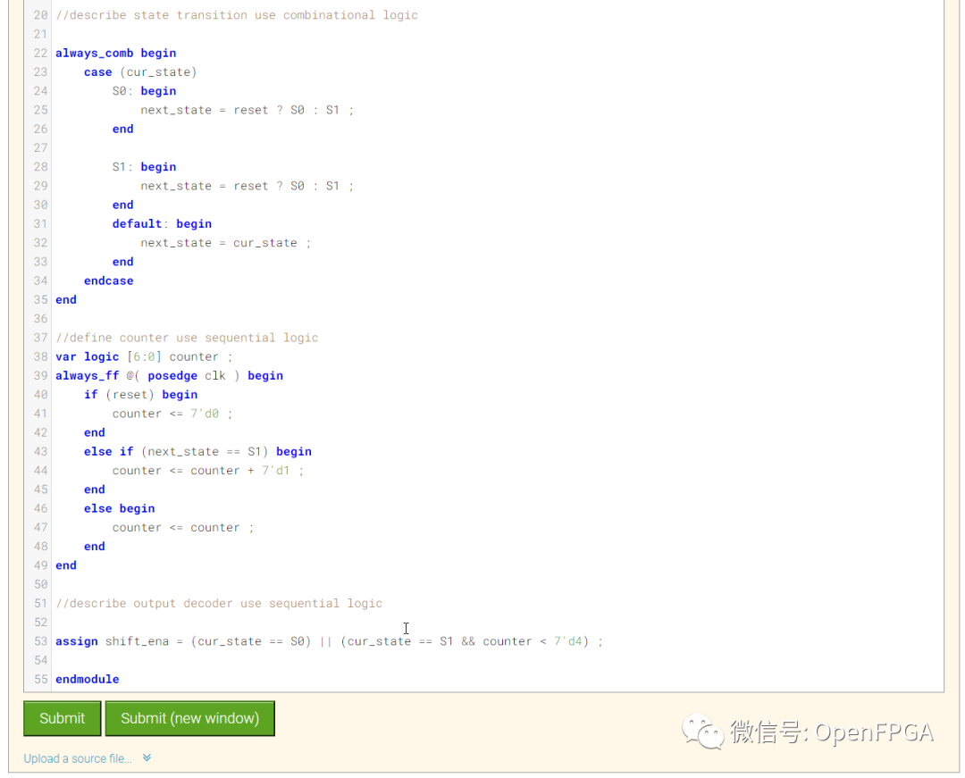
點擊Submit,等待一會就能看到下圖結果:
注意圖中無波形。
這一題就結束了。
Problem 155-review2015_fsm
題目說明
本題實現復雜計數器的第四個組件。
在此題之前,我們已經分別實現了 FSM:Enable shift register 以及 FSM:1101 序列檢測器。接下來我們繼續前進,實現這個復雜計數器的完整 FSM。
復雜計數器需要如下這些功能特性:
在數據流中檢測到特定序列后啟動計數器,該序列為: 1101將 4bits 數據輸入移位寄存器,作為計數器的初值等待計數器結束計數告知上層應用計數完成,并等待用戶通過 ack 信號確認在本題練習中,只需要實現控制狀態機,不需要實現數據通路,比如計數器本身以及數據比較器等。
數據流從模塊的 data 信號輸入,當檢測到 1101 序列后,狀態機需要置高輸出信號 shft_ena 并保持 4 個周期(用于將接下來 4bit 數據輸入移位寄存器)。
之后,狀態機置高 counting 信號,表示其正在等待計數器完成計數,當計數器完成計數輸出 done_counting 信號后,counting 信號置低。
再此后,狀態機置高 done 信號通知上層應用計數器計數完成,等待 ack 信號置高后,狀態機清除 done 信號,返回空閑狀態等待捕獲下一個 1101 序列。
本題給出了一個期望輸入輸出的例子。圖中的斜線代表當前信號為 'X', 表示狀態機不關心該信號當前的值。比如圖例中,一旦 FSM 檢測到 1101 序列后,在此次計數器事件完成前,對于當前的數據流不再關心。

模塊端口聲明
moduletop_module(
inputclk,
inputreset,//Synchronousreset
inputdata,
outputshift_ena,
outputcounting,
inputdone_counting,
outputdone,
inputack);
題目解析
狀態轉移圖

moduletop_module(
inputlogicclk,
inputlogicreset,//Synchronousreset
inputlogicdata,
outputlogicshift_ena,
outputlogiccounting,
inputlogicdone_counting,
outputlogicdone,
inputlogicack
);
//definestate
typedefenumlogic[2:0]{idle=3'd1,S0=3'd2,S1=3'd3,
S2=3'd4,shif=3'd5,count=3'd6,
waite=3'd7
}state_def;
state_defcur_state,next_state;
//describestatetransitionusecombinationallogic
always_combbegin
case(cur_state)
idle:begin
next_state=data?S0:idle;
end
S0:begin
next_state=data?S1:idle;
end
S1:begin
next_state=data?S1:S2;
end
S2:begin
next_state=data?shif:idle;
end
shif:begin
next_state=counter
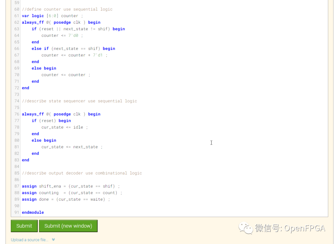
點擊Submit,等待一會就能看到下圖結果:
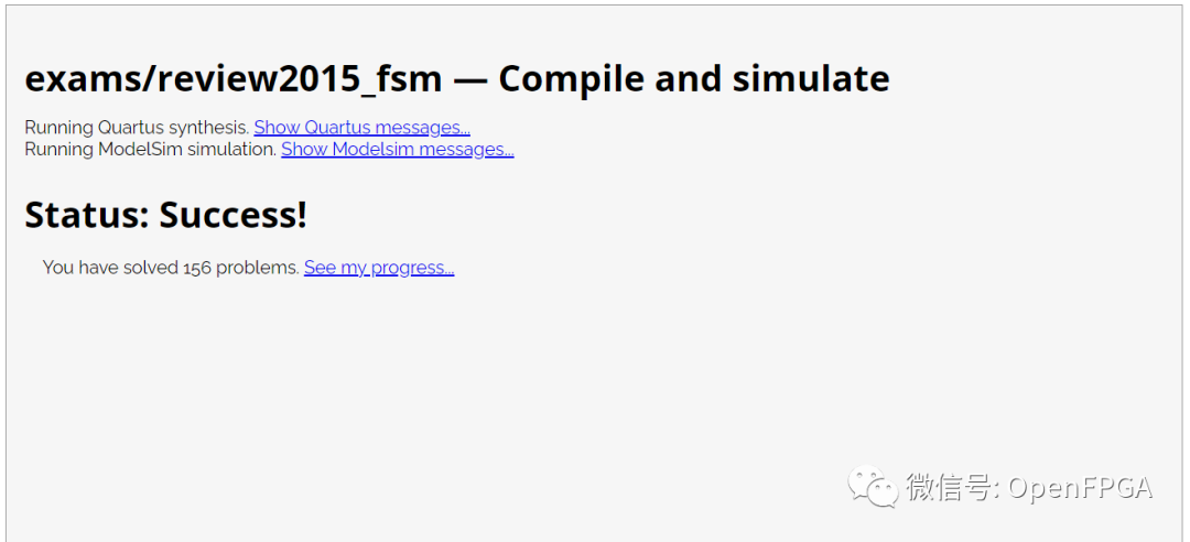
注意圖中無參考波形。
這一題就結束了。
Problem 156-review2015_fancytimer
題目說明
終于到了完整構建復雜計數器的時候,整體功能已經在上題中討論,這里不再贅述。
在數據流中檢測到序列 1101 后,電路需要將接下來的 4bit 數據移入移位寄存器。4bit 數據決定了計數器的計數周期,稱為 delay[3:0]。首先到達的比特作為數據的高位。
之后,狀態機置高 counting 信號,表示其正在等待計數器完成計數。在 FSM 中增加計數器狀態,計數周期為 (delay[3:0] + 1 )* 1000 個時鐘周期。比如 delay = 0 時,計數值為 1000 個周期。delay = 5 代表 6000 個周期。同時輸出 count 當前剩余的計數周期,輸出當前剩余計數周期的千位(比如,還剩1000個周期輸出 1,還剩 999 個周期時輸出 0)。當計數停止后,count 的輸出可以為任意數。
當計數完成后,電路置高 done 信號通知上層應用計數器計數完成,等待 ack 信號置高后,狀態機清除 done 信號,返回空閑狀態等待捕獲下一個 1101 序列。
本題給出了一個期望輸入輸出的例子。圖中的斜線代表當前信號為 'X', 表示狀態機不關心該信號當前的值。比如圖例中,一旦 FSM 檢測到 1101 序列并讀取 delay[3:0] 后,在此次計數器事件完成前,對于當前的數據流不再關心。
在圖例中,電路計數周期為 2000 ,因為 delay[3:0] 數值為 4'b0001 。在后續的第二個計數周期中,因為 delay[3:0] = 4‘b1110,所以計數周期為 15000。
 圖片來自HDLBits
模塊端口聲明
moduletop_module(
inputclk,
inputreset,//Synchronousreset
inputdata,
output[3:0]count,
outputcounting,
outputdone,
inputack);
題目解析
moduletop_module(
inputlogicclk,
inputlogicreset,//Synchronousreset
inputlogicdata,
outputlogic[3:0]count,
outputlogiccounting,
outputlogicdone,
inputlogicack
);
//definestate
typedefenumlogic[2:0]{idle=3'd1,S0=3'd2,S1=3'd3,
S2=3'd4,shif=3'd5,count_t=3'd6,
waite=3'd7
}state_def;
state_defcur_state,next_state;
//describestatetransitionusecombinationallogic
always_combbegin
case(cur_state)
idle:begin
next_state=data?S0:idle;
end
S0:begin
next_state=data?S1:idle;
end
S1:begin
next_state=data?S1:S2;
end
S2:begin
next_state=data?shif:idle;
end
shif:begin
next_state=counter_shif=1000&&counter<=?1999)begin
????????counter_delay?=?4'd1;
????end
????else?if(counter?>=2000&&counter<=?2999)begin
????????counter_delay?=?4'd2;
????end
????else?if(counter?>=3000&&counter<=?3999)begin
????????counter_delay?=?4'd3;
????end
????else?if(counter?>=4000&&counter<=?4999)begin
????????counter_delay?=?4'd4;
????end
????else?if(counter?>=5000&&counter<=?5999)begin
????????counter_delay?=?4'd5;
????end
????else?if(counter?>=6000&&counter<=?6999)begin
????????counter_delay?=?4'd6;
????end
????else?if(counter?>=7000&&counter<=?7999)begin
????????counter_delay?=?4'd7;
????end
????else?if(counter?>=8000&&counter<=?8999)begin
????????counter_delay?=?4'd8;
????end
????else?if(counter?>=9000&&counter<=?9999)begin
????????counter_delay?=?4'd9;
????end
????else?if(counter?>=10000&&counter<=?10999)begin
????????counter_delay?=?4'd10;
????end
????else?if(counter?>=11000&&counter<=?11999)begin
????????counter_delay?=?4'd11;
????end
????else?if(counter?>=12000&&counter<=?12999)begin
????????counter_delay?=?4'd12;
????end
????else?if(counter?>=13000&&counter<=?13999)begin
????????counter_delay?=?4'd13;
????end
????else?if(counter?>=14000&&counter<=?14999)begin
????????counter_delay?=?4'd14;
????end
????else?begin
????????counter_delay?=?4'd15;
????end
end?????
endmodule
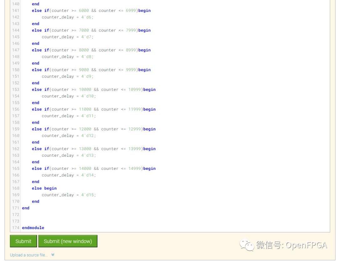
點擊Submit,等待一會就能看到下圖結果:

注意圖中無波形。
這一題就結束了。
Problem 157-review2015_fsmonehot
題目說明
給定以下具有 3 個輸入、3 個輸出和 10 個狀態的狀態機:
 圖片來自HDLBits
假定使用以下one-hot編碼, 通過檢查推導出下一狀態邏輯方程和輸出邏輯方程: (S, S1, S11, S110, B0, B1, B2, B3, Count, Wait) = (10'b0000000001, 10 'b0000000010, 10'b0000000100, ..., 10'b1000000000)
假設采用one-hot編碼,通過檢查推導狀態轉換和輸出邏輯方程。僅為該狀態機實現狀態轉換邏輯和輸出邏輯(組合邏輯部分)。(測試臺將使用非熱輸入進行測試,以確保不會嘗試做更復雜的事情。請參閱fsm3onehot用于描述單熱狀態機“通過檢查”推導邏輯方程的含義。)
編寫生成以下等式的代碼:
B3_next ,B2 狀態的次態(原題寫的 B1,應該為筆誤)
S_next
S1_next
Count_next
以及下列輸出信號
done
counting
shift_ena
模塊端口聲明
moduletop_module(
inputd,
inputdone_counting,
inputack,
input[9:0]state,//10-bitone-hotcurrentstate
outputB3_next,
outputS_next,
outputS1_next,
outputCount_next,
outputWait_next,
outputdone,
outputcounting,
outputshift_ena
);
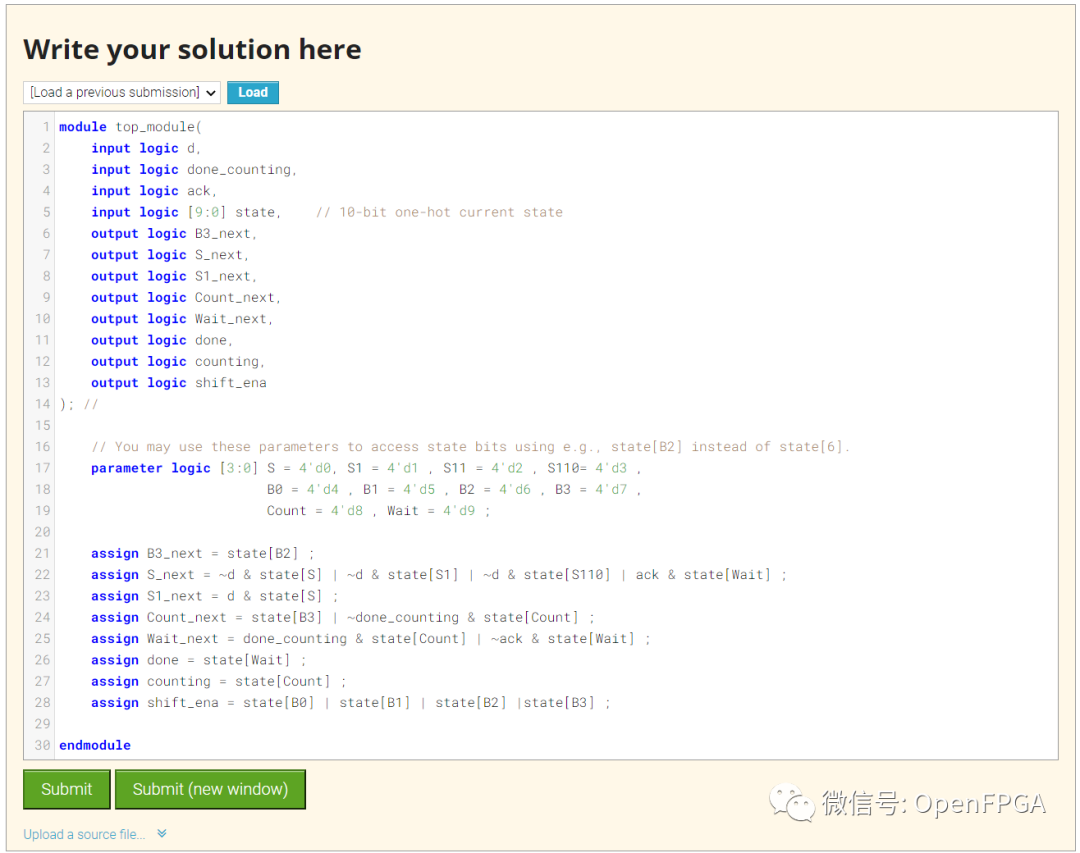
題目解析
moduletop_module(
inputlogicd,
inputlogicdone_counting,
inputlogicack,
inputlogic[9:0]state,//10-bitone-hotcurrentstate
outputlogicB3_next,
outputlogicS_next,
outputlogicS1_next,
outputlogicCount_next,
outputlogicWait_next,
outputlogicdone,
outputlogiccounting,
outputlogicshift_ena
);//
//Youmayusetheseparameterstoaccessstatebitsusinge.g.,state[B2]insteadofstate[6].
parameterlogic[3:0]S=4'd0,S1=4'd1,S11=4'd2,S110=4'd3,
B0=4'd4,B1=4'd5,B2=4'd6,B3=4'd7,
Count=4'd8,Wait=4'd9;
assignB3_next=state[B2];
assignS_next=~d&state[S]|~d&state[S1]|~d&state[S110]|ack&state[Wait];
assignS1_next=d&state[S];
assignCount_next=state[B3]|~done_counting&state[Count];
assignWait_next=done_counting&state[Count]|~ack&state[Wait];
assigndone=state[Wait];
assigncounting=state[Count];
assignshift_ena=state[B0]|state[B1]|state[B2]|state[B3];
endmodule
點擊Submit,等待一會就能看到下圖結果:
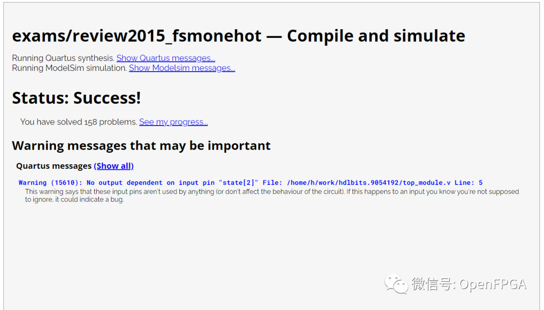
注意圖中的Ref是參考波形,Yours是你的代碼生成的波形,網站會對比這兩個波形,一旦這兩者不匹配,仿真結果會變紅。
這一題就結束了。
總結
今天的幾道題就結束了,今天是大型電路的設計思路,分模塊設計。
審核編輯:劉清
-
計數器
+關注
關注
32文章
2259瀏覽量
94802 -
時序電路
+關注
關注
1文章
114瀏覽量
21723 -
狀態機
+關注
關注
2文章
492瀏覽量
27593 -
Verilog語言
+關注
關注
0文章
113瀏覽量
8284
原文標題:HDLBits: 在線學習 SystemVerilog(二十二)-Problem 151-157(構建大型電路)
文章出處:【微信號:Open_FPGA,微信公眾號:OpenFPGA】歡迎添加關注!文章轉載請注明出處。
發布評論請先 登錄
相關推薦
SystemVerilog 的VMM驗證方法學教程教材
[啟芯公開課] SystemVerilog for Verification
round robin 的 systemverilog 代碼
做FPGA工程師需要掌握SystemVerilog嗎?
(2)打兩拍systemverilog與VHDL編碼 精選資料分享
SystemVerilog Assertion Handbo
SystemVerilog的斷言手冊
基于事件結構的SystemVerilog指稱語義
SystemVerilog的正式驗證和混合驗證
Systemverilog中的Driving Strength講解


 SystemVerilog構建大型電路


評論