串行 FIR 濾波器設(shè)計
設(shè)計說明
設(shè)計參數(shù)不變,與并行 FIR 濾波器參數(shù)一致。 即,輸入頻率為 7.5 MHz 和 250 KHz 的正弦波混合信號,經(jīng)過 FIR 濾波器后,高頻信號 7.5MHz 被濾除,只保留 250KMHz 的信號。
輸入頻率: 7.5MHz 和 250KHz
采樣頻率: 50MHz
阻帶: 1MHz-6MHz
階數(shù): 15 (N=15)
串行設(shè)計,就是在 16 個時鐘周期內(nèi)對 16 個延時數(shù)據(jù)分時依次進行乘法、加法運算,然后在時鐘驅(qū)動下輸出濾波值。 考慮到 FIR 濾波器系數(shù)的對稱性,計算一個濾波輸出值的周期可以減少到 8 個。 串行設(shè)計時每個周期只進行一次乘法運算,所以設(shè)計中只需一個乘法器即可。 此時數(shù)據(jù)需要每 8 個時鐘周期有效輸入一次,但是為了保證輸出信號頻率的正確性,工作時鐘需要為采樣頻率的 8 倍,即 400MHz。 這種方法的優(yōu)點是資源耗費少,但是工作頻率要求高,數(shù)據(jù)不能持續(xù)輸出。
串行設(shè)計
設(shè)計中使用到的乘法器模塊代碼,可參考之前流水線式設(shè)計的乘法器。
為方便快速仿真,也可以直接使用乘號 “*” 完成乘法運算,設(shè)計中加入宏定義 SAFE_DESIGN 來選擇使用哪種乘法器。
FIR 濾波器系數(shù)可由 matlab 生成,具體見附錄。
/**********************************************************
>> Description : fir study with serial tech
>> V190403 : Fs:50Mhz, fstop:1-6Mhz, order:16, sys clk:400MHz
***********************************************************/
`define SAFE_DESIGN
module fir_serial_low(
input rstn,
input clk, // 系統(tǒng)工作時鐘,400MHz
input en , // 輸入數(shù)據(jù)有效信號
input [11:0] xin, // 輸入混合頻率的信號數(shù)據(jù)
output valid, // 輸出數(shù)據(jù)有效信號
output [28:0] yout // 輸出數(shù)據(jù)
);
//delay of input data enable
reg [11:0] en_r ;
always @(posedge clk or negedge rstn) begin
if (!rstn) begin
en_r[11:0] <= 'b0 ;
end
else begin
en_r[11:0] <= {en_r[10:0], en} ;
end
end
//fir coeficient
wire [11:0] coe[7:0] ;
assign coe[0] = 12'd11 ;
assign coe[1] = 12'd31 ;
assign coe[2] = 12'd63 ;
assign coe[3] = 12'd104 ;
assign coe[4] = 12'd152 ;
assign coe[5] = 12'd198 ;
assign coe[6] = 12'd235 ;
assign coe[7] = 12'd255 ;
//(1) 輸入數(shù)據(jù)移位部分
reg [2:0] cnt ;
integer i, j ;
always @(posedge clk or negedge rstn) begin
if (!rstn) begin
cnt <= 3'b0 ;
end
else if (en || cnt != 0) begin
cnt <= cnt + 1'b1 ; //8個周期計數(shù)
end
end
reg [11:0] xin_reg[15:0];
always @(posedge clk or negedge rstn) begin
if (!rstn) begin
for (i=0; i<16; i=i+1) begin
xin_reg[i] <= 12'b0;
end
end
else if (cnt == 3'd0 && en) begin //每8個周期讀入一次有效數(shù)據(jù)
xin_reg[0] <= xin ;
for (j=0; j<15; j=j+1) begin
xin_reg[j+1] <= xin_reg[j] ; // 數(shù)據(jù)移位
end
end
end
//(2) 系數(shù)對稱,16個移位寄存器數(shù)據(jù)進行首位相加
reg [11:0] add_a, add_b ;
reg [11:0] coe_s ;
wire [12:0] add_s ;
wire [2:0] xin_index = cnt>=1 ? cnt-1 : 3'd7 ;
always @(posedge clk or negedge rstn) begin
if (!rstn) begin
add_a <= 13'b0 ;
add_b <= 13'b0 ;
coe_s <= 12'b0 ;
end
else if (en_r[xin_index]) begin //from en_r[1]
add_a <= xin_reg[xin_index] ;
add_b <= xin_reg[15-xin_index] ;
coe_s <= coe[xin_index] ;
end
end
assign add_s = {add_a} + {add_b} ;
//(3) 乘法運算,只用一個乘法
wire [24:0] mout ;
`ifdef SAFE_DESIGN
wire en_mult ;
wire [3:0] index_mult = cnt>=2 ? cnt-1 : 4'd7 + cnt[0] ;
mult_man #(13, 12) u_mult_single //例化自己設(shè)計的流水線乘法器
(.clk (clk),
.rstn (rstn),
.data_rdy (en_r[index_mult]), //注意數(shù)據(jù)時序?qū)?yīng)
.mult1 (add_s),
.mult2 (coe_s),
.res_rdy (en_mult),
.res (mout)
);
`else
always @(posedge clk or negedge rstn) begin
if (!rstn) begin
mout <= 25'b0 ;
end
else if (|en_r[8:1]) begin
mout <= coe_s * add_s ; //直接乘
end
end
wire en_mult = en_r[2];
`endif
//(4) 積分累加,8組25bit數(shù)據(jù) -> 1組 29bit 數(shù)據(jù)
reg [28:0] sum ;
reg valid_r ;
//mult output en counter
reg [4:0] cnt_acc_r ;
always @(posedge clk or negedge rstn) begin
if (!rstn) begin
cnt_acc_r <= 'b0 ;
end
else if (cnt_acc_r == 5'd7) begin //計時8個周期
cnt_acc_r <= 'b0 ;
end
else if (en_mult || cnt_acc_r != 0) begin //只要en有效,計時不停
cnt_acc_r <= cnt_acc_r + 1'b1 ;
end
end
always @(posedge clk or negedge rstn) begin
if (!rstn) begin
sum <= 29'd0 ;
valid_r <= 1'b0 ;
end
else if (cnt_acc_r == 5'd7) begin //在第8個累加周期輸出濾波值
sum <= sum + mout;
valid_r <= 1'b1 ;
end
else if (en_mult && cnt_acc_r == 0) begin //初始化
sum <= mout ;
valid_r <= 1'b0 ;
end
else if (cnt_acc_r != 0) begin //acculating between cycles
sum <= sum + mout ;
valid_r <= 1'b0 ;
end
end
//時鐘鎖存有效的輸出數(shù)據(jù),為了讓輸出信號不是那么頻繁的變化
reg [28:0] yout_r ;
always @(posedge clk or negedge rstn) begin
if (!rstn) begin
yout_r <= 'b0 ;
end
else if (valid_r) begin
yout_r <= sum ;
end
end
assign yout = yout_r ;
//(5) 輸出數(shù)據(jù)有效延遲,即濾波數(shù)據(jù)丟掉前15個濾波值
reg [4:0] cnt_valid ;
always @(posedge clk or negedge rstn) begin
if (!rstn) begin
cnt_valid <= 'b0 ;
end
else if (valid_r && cnt_valid != 5'd16) begin
cnt_valid <= cnt_valid + 1'b1 ;
end
end
assign valid = (cnt_valid == 5'd16) & valid_r ;
endmodule
測試平臺
testbench 編寫如下,主要功能就是不間斷連續(xù)的輸入 250KHz 與 7.5MHz 的正弦波混合信號數(shù)據(jù)。 輸入的混合信號數(shù)據(jù)也可由 matlab 生成,具體見附錄。
其中,工作頻率為 400MHz,但輸入數(shù)據(jù)和輸入數(shù)據(jù)有效信號應(yīng)當(dāng)都保持 50MHz 的頻率輸入。
module test ;
    //input
    reg          clk ;
    reg          rst_n ;
    reg          en ;
    reg  [11:0]  xin ;
    //output
    wire [28:0]  yout ;
    wire         valid ;


    parameter    SIMU_CYCLE   = 64'd1000 ;
    parameter    SIN_DATA_NUM = 200 ;


//=====================================
// 8*50MHz clk generating
    localparam   TCLK_HALF     = (10_000 >>3);
    initial begin
        clk = 1'b0 ;
        forever begin
            # TCLK_HALF clk = ~clk ;
        end
     end

//============================
//  reset and finish
    initial begin
        rst_n = 1'b0 ;
        # 30        rst_n = 1'b1 ;
        # (TCLK_HALF * 2 * 8  * SIMU_CYCLE) ;
        $finish ;
    end

//=======================================
// read cos data into register
    reg          [11:0] stimulus [0: SIN_DATA_NUM-1] ;
    integer      i ;
    initial begin
        $readmemh("../tb/cosx0p25m7p5m12bit.txt", stimulus) ;
        en = 0 ;
        i = 0 ;
        xin = 0 ;
        # 200 ;
        forever begin
            repeat(7)  @(negedge clk) ; //空置7個周期,第8個周期給數(shù)據(jù)
            en          = 1 ;
            xin         = stimulus[i] ;
            @(negedge clk) ;
            en          = 0 ;         //輸入數(shù)據(jù)有效信號只持續(xù)一個周期即可
            if (i == SIN_DATA_NUM-1)  i = 0 ;
            else  i = i + 1 ;
        end
    end

    fir_serial_low       u_fir_serial (
        .clk         (clk),
        .rstn        (rst_n),
        .en          (en),
        .xin         (xin),
        .valid       (valid),
        .yout        (yout));


endmodule
仿真結(jié)果
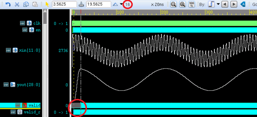
由下圖仿真結(jié)果可知,經(jīng)過 FIR 濾波器后的信號只有一種低頻率信號(250KHz),高頻信號(7.5MHz)被濾除了。 為了波形更加的美觀,取 16 個之后的濾波數(shù)據(jù)作為有效輸出。

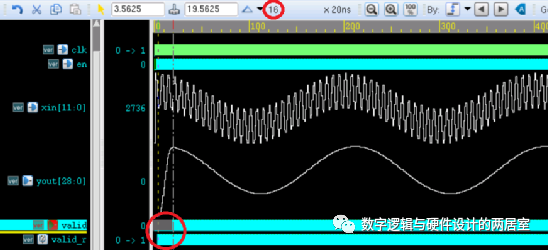
波形局部放大后如下圖所示,此時輸入數(shù)據(jù)有效信號 en 與輸出數(shù)據(jù)有效信號 valid 是周期(50MHz)相同的脈沖信號,不是持續(xù)有效的。 但工作時鐘為 400MHz,所以輸出也會呈現(xiàn)為 50MHz 采樣頻率下的 250KHz 頻率的正弦波信號。

生成 FIR 濾波器系數(shù)
打開 matlab,在命令窗口輸入命令: fdatool。
然后會打開如下窗口,按照 FIR 濾波器參數(shù)進行設(shè)置,如下所示。
這里選擇的 FIR 實現(xiàn)方法是最小二乘法(Least-squares),不同的實現(xiàn)方式濾波效果也不同。

點擊File -> Export
將濾波器參數(shù)輸出,存到變量 coef 中,如下圖所示。

此時 coef 變量應(yīng)該是浮點型數(shù)據(jù)。 對其進行一定倍數(shù)的相乘擴大,然后取其近似的定點型數(shù)據(jù)作為設(shè)計中的 FIR 濾波器參數(shù)。 這里取擴大倍數(shù)為 2048,結(jié)果如下所示。

生成輸入的混合信號
利用 matlab 生成混合的輸入信號參考代碼如下。
信號為無符號定點型數(shù)據(jù),位寬寬度為 12bit,存于文件 'cosx0p25m7p5m12bit.txt' 。
clear all;close all;clc;
%=======================================================
% generating a cos wave data with txt hex format
%=======================================================


fc          = 0.25e6 ;      % 中心頻率
fn          = 7.5e6 ;       % 雜波頻率
Fs          = 50e6 ;        % 采樣頻率
T           = 1/fc ;        % 信號周期
Num         = Fs * T ;      % 周期內(nèi)信號采樣點數(shù)
t           = (0:Num-1)/Fs ;      % 離散時間
cosx        = cos(2*pi*fc*t) ;    % 中心頻率正弦信號
cosn        = cos(2*pi*fn*t) ;    % 雜波信號
cosy        = mapminmax(cosx + cosn) ;     %幅值擴展到(-1,1) 之間
cosy_dig    = floor((2^11-1) * cosy + 2^11) ;     %幅值擴展到 0~4095
fid         = fopen('cosx0p25m7p5m12bit.txt', 'wt') ;  %寫數(shù)據(jù)文件
fprintf(fid, '%x\\n', cosy_dig) ;
fclose(fid) ;

%時域波形
figure(1);
subplot(121);plot(t,cosx);hold on ;
plot(t,cosn) ;
subplot(122);plot(t,cosy_dig) ;

%頻域波形
fft_cosy    = fftshift(fft(cosy, Num)) ;
f_axis      = (-Num/2 : Num/2 - 1) * (Fs/Num) ;
figure(5) ;
plot(f_axis, abs(fft_cosy)) ;
-
濾波器
+關(guān)注
關(guān)注
161文章
7817瀏覽量
178126 -
FIR
+關(guān)注
關(guān)注
4文章
146瀏覽量
33173 -
信號
+關(guān)注
關(guān)注
11文章
2791瀏覽量
76764 -
Verilog
+關(guān)注
關(guān)注
28文章
1351瀏覽量
110100 -
串行
+關(guān)注
關(guān)注
0文章
237瀏覽量
33847
發(fā)布評論請先 登錄
相關(guān)推薦
串行結(jié)構(gòu)的FIR濾波器設(shè)計(含文檔 代碼資料)
并行FIR濾波器Verilog設(shè)計
什么是fir數(shù)字濾波器 什么叫FIR濾波器
FIR結(jié)構(gòu)IQ串行處理RRC濾波器

串行結(jié)構(gòu)的FIR濾波器設(shè)計 (含有代碼 文檔資料)
詳解FIR濾波器和IIR濾波器的區(qū)別
基于FPGA的橫向FIR濾波器設(shè)計詳解
FIR濾波器和IIR濾波器的區(qū)別與聯(lián)系
Verilog串行FIR濾波器設(shè)計


 Verilog串行FIR濾波器設(shè)計


評論