1.Introduction
This document indicates the hardware/software design notes to migrate from Beckhoff ET1100 ESC solution to AX58100 ESC solution.
2.FunctionsOverview
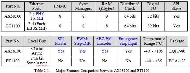
The AX58100 is a 2/3-port EtherCAT Slave Controller (ESC), licensed from Beckhoff Automation, with two integrated Fast Ethernet PHYs which support 100Mbps full-duplex operation and HP Auto-MDIX. AX58100 supports 9 Kbytes Process Data RAM, 8 Fieldbus Memory Management Units (FMMUs), 8 Sync-Managers and a 64-bit Distributed Clock.
Compared to other EtherCAT slave controller solutions, the AX58100 integrates two embedded Fast Ethernet PHYs which can support both copper and fiber industrial Ethernet applications and supports some additional interfaces such as Pulse Width Modulation (PWM), Incremental (ABZ)/Hall Encoder, SPI master, 32 Digital I/O, Emergency Stop Input, etc. for designers to easily implement AX58100 on different EtherCAT industrial fieldbus applications without extra microprocessor. The AX58100 provides SPI slave and Local bus Process Data Interfaces (PDI) to provide an easy way for system designers to implement the standard EtherCAT communication functionalities on those traditional non-EtherCAT MCU and DSP industrial platforms.
The AX58100 provides a cost-effective EtherCAT slave controller solution for industrial automation, motion/motor/Digital IO control, Digital to Analog (DAC)/Analog to Digital (ADC) converters control, sensors data acquisition, robotics, etc. industrial Ethernet fieldbus applications.
The following is the major features comparison between AX58100 and Beckhoff ET1100 ESC solutions.
2-1. BlockDiagram
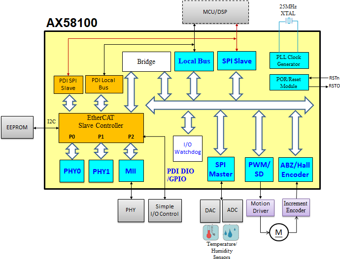
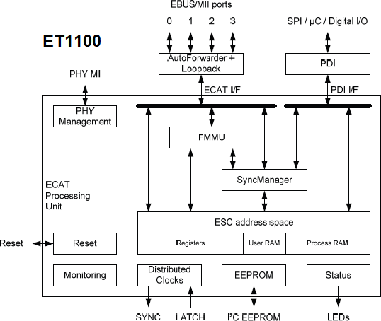
The following are the block diagrams of AX58100 and ET1100.
2-2. ApplicationDiagram
The following are the typical applications diagrams of AX58100 and ET1100. The AX58100 integrates additional interfaces such as Pulse Width Modulation (PWM), ABZ/Hall Encoder, SPI master, 32 Digital I/O, Emergency Stop Input, etc. for designers to easily implement AX58100 on different EtherCAT industrial fieldbus applications without extra microprocessor.
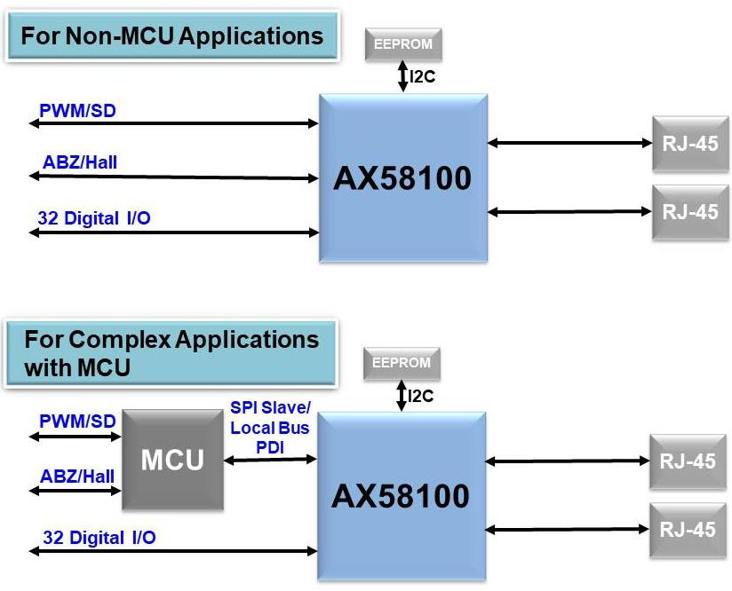
Figure2-3. AX58100 Application Diagram
Figure2-4. ET1100 Application Diagram
3.HardwareTransition
This section indicates the hardware design considerations while migrating from Beckhoff ET1100 ESC solution to AX58100 ESC solution.
3-1. Bootstrap Hardware ConfigurationPins
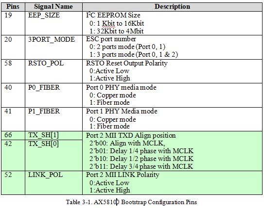
The AX58100 supports five multi-function bootstrap pins (pin 19, 20, 58, 40, and 41) for five hardware configurations, i.e. external I2C EEPROM size, ESC supported port number, RSTO polarity and integrated port 0/1 PHY media mode; and supports other three multi-function bootstrap pins (pin 42, 52, 66) for the configuration of port 2 MII signals. User needs to utilize an external resistor to pull up/down these bootstrap pins for correct AX58100 hardware configuration.
Beckhoff supports different hardware configuration pins based on the ET1100 product design specification. Please refer to Beckhoff ET1100 datasheet for details.
3-2. EthernetPorts
The AX58100 ESC, which is licensed from Beckhoff Automation, supports two embedded PHYs and an optional MII interface for flexible network topology. The embedded Fast Ethernet PHYs support 100Mbps full-duplex operation and HP Auto-MDIX, and are fully compliant with the 100BASE-TX and 100BASE-FX Ethernet standards such as IEEE 802.3u, and ANSI X3.263- 1995 (FDDI-TP-PMD) for both copper and fiber industrial Ethernet applications.
The optional MII interface of AX58100 ESC is optimized for low processing/forwarding delays by omitting a transmit FIFO. To allow this, the ESC has additional requirements to Ethernet PHY, which is easily accomplished by several PHY vendors. Please refer to Beckhoff’s PHY Selection Guide to select a proper Ethernet PHY.
AX58100 Port 0 and Port 1 integrate embedded Ethernet PHYs, and Port 2 is an optional MII interface which are multi-function pins shared with others interfaces (i.e. PWM, Hall, Local Bus, Digital I/O). Packets are forwarded in the following order:
Port 0 -> EtherCAT Processing Unit -> Port 1 -> Port 2
AX58100 supports six Bootstrap pins (pin 20, 40-42, 52 and 66) for Ethernet ports hardware configurations. Please refer to Table 3-1for details.
The following is the principle connection between AX58100 Port 2 MII interface and Ethernet PHY. The clock source of the Ethernet PHYs and ESC must be the same quartz. The TX_CLK is not connected because the ESCs do not incorporate a TX FIFO. The TX signals can be delayed inside the ESC by setting AX58100 TX_SH[1:0] bootstrap pins for TX_CLK phase shift compensation. The LINK is connected to the PHY LED output indicating a 100 Mbps (Full Duplex) link.
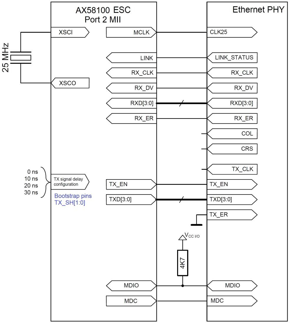
Figure3-1.The principle connection between AX58100 Port 2 MII interface and EthernetPHY
3-3.Digital I/O PDI
由于篇幅限制無法完整顯示整篇文章,若需獲取整份PDF文檔,或其他相關AX58100資料,請發Mail至以下地址:info@chipreal.com
-
ASIX
+關注
關注
0文章
11瀏覽量
9319 -
ethercat
+關注
關注
18文章
711瀏覽量
38741 -
ax58100
+關注
關注
0文章
12瀏覽量
7802 -
ET1100
+關注
關注
0文章
2瀏覽量
2248
發布評論請先 登錄
相關推薦
ADS1672轉換輸出,DRDY管腳一直是高電平,為什么?
ADC122s021通道二轉換輸出數據總是跳動,怎么解決?
用msp430j接收到ADS1292轉換后的數據該如何將它用波形顯示?
ADS1256轉換后的數據規律失真的原因?怎么解決?
如何選擇RS232轉換器?RS232與RS485區別
使用Resizer在DM6446上進行去隔行掃描和YUV 4:2:2到4:2:0轉換

是否有可能在軟件中重新配置XMC4800的兩個MII端口,使其用于E-BUS通信?
TCAL6416 16位轉換I2C總線,SMBus I/O擴展器數據表

TCAL6408 8位轉換I2C總線,SMBus I/O擴展器數據表


 ET1100轉換AX58100的設計要求及應用指南


評論