嗨嘍,大家好,我是程序猿老王,程序猿老王就是我。
今天給大家全面的分析一下u-boot啟動流程。整理這篇文章花費時間較長,中間很長時間未更新,希望這篇文章對大家有所幫助。
本章主要是詳細的分析一下uboot的啟動流程,理清uboot是如何啟動的。通過對uboot啟動流程的梳理,我們就可以掌握一些外設是在哪里被初始化的,這樣當我們需要修改這些外設驅動的時候就會心里有數。另外,通過分析uboot的啟動流程可以了解Linux內核是如何被啟動的。
在看本章之前,個人建議先去看一下前幾篇文章。對u-boot的開發(fā)環(huán)境搭建、u-boot整體移植和u-boot下網絡調試有一點了解后,再來看本篇文章,這樣可能比較容易看明白。
本章主要是詳細的分析一下uboot的啟動流程,理清uboot是如何啟動的。通過對uboot啟動流程的梳理,我們就可以掌握一些外設是在哪里被初始化的,這樣當我們需要修改這些外設驅動的時候就會心里有數。另外,通過分析uboot的啟動流程可以了解Linux內核是如何被啟動的。
一、u-boot啟動詳細函數調用流程
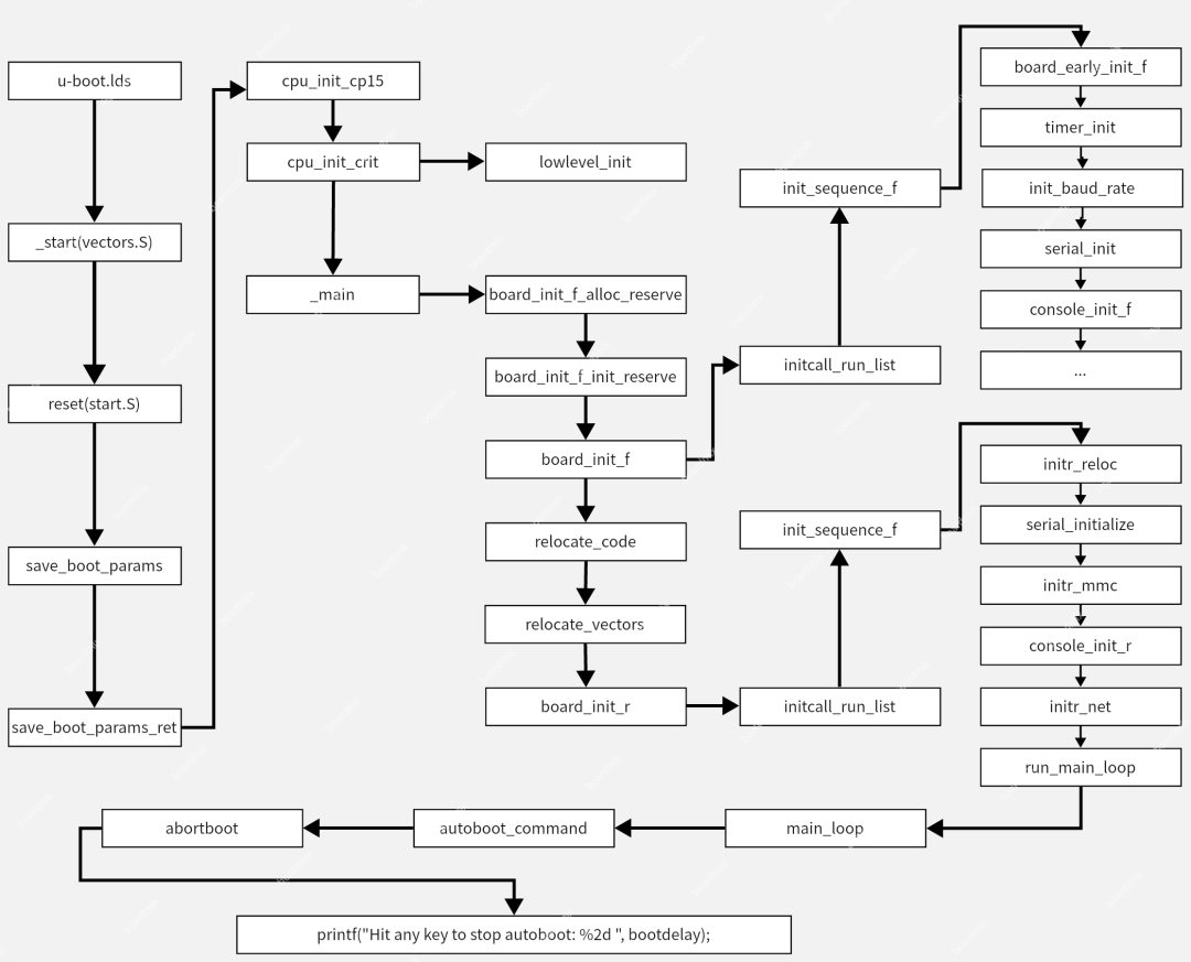
首先給大家先看一下,u-boot啟動從入口函數到啟動內核的詳細函數調用流程的層級關系圖,對u-boot啟動的整體有一個快速了解,后面會詳細介紹各個函數的作用。
u-boot:啟動詳細的代碼調用流程
u-boot.lds:(arch/arm/cpu/u-boot.lds)
|-- >_start:(arch/arm/lib/vectors.S)
|-- >reset(arch/arm/cpu/armv7/start.S)
|-- >save_boot_params(arch/arm/cpu/armv7/start.S)/*將引導參數保存到內存中*/
|-- >save_boot_params_ret(arch/arm/cpu/armv7/start.S)
|-- >cpu_init_cp15(arch/arm/cpu/armv7/start.S)/*初始化*/
|-- >cpu_init_crit(arch/arm/cpu/armv7/start.S)
|-- >lowlevel_init(arch/arm/cpu/armv7/lowlevel_init.S)
|-- >_main(arch/arm/lib/crt0.S)
|-- >board_init_f_alloc_reserve(common/init/board_init.c)/*為u-boot的gd結構體分配空間*/
|-- >board_init_f_init_reserve(common/init/board_init.c) /*將gd結構體清零*/
|-- >board_init_f(common/board_f.c)
|-- >initcall_run_list(include/initcall.h) /*初始化序列函數*/
|-- >init_sequence_f[](common/board_f.c) /* 初始化序列函數數組 */
|-- >board_early_init_f(board/freescale/mx6ull_toto/mx6ull_toto.c)/*初始化串口的IO配置*/
|-- >timer_init(arch/arm/imx-common/timer.c) /*初始化內核定時器,為uboot提供時鐘節(jié)拍*/
|-- >init_baud_rate(common/board_f.c) /*初始化波特率*/
|-- >serial_init(drivers/serial/serial.c) /*初始化串口通信設置*/
|-- >console_init_f(common/console.c) /*初始化控制臺*/
|-- >...
|-- >relocate_code(arch/arm/lib/relocate.S) /*主要完成鏡像拷貝和重定位*/
|-- >relocate_vectors(arch/arm/lib/relocate.S)/*重定位向量表*/
|-- >board_init_r(common/board_r.c)/*板級初始化*/
|-- >initcall_run_list(include/initcall.h)/*初始化序列函數*/
|-- >init_sequence_r[](common/board_f.c)/*序列函數*/
|-- >initr_reloc(common/board_r.c) /*設置 gd- >flags,標記重定位完成*/
|-- >serial_initialize(drivers/serial/serial-uclass.c)/*初始化串口*/
|-- >serial_init(drivers/serial/serial-uclass.c) /*初始化串口*/
|-- >initr_mmc(common/board_r.c) /*初始化emmc*/
|-- >mmc_initialize(drivers/mmc/mmc.c)
|-- >mmc_do_preinit(drivers/mmc/mmc.c)
|-- >mmc_start_init(drivers/mmc/mmc.c)
|-- >console_init_r(common/console.c) /*初始化控制臺*/
|-- >interrupt_init(arch/arm/lib/interrupts.c) /*初始化中斷*/
|-- >initr_net(common/board_r.c) /*初始化網絡設備*/
|-- >eth_initialize(net/eth-uclass.c)
|-- >eth_common_init(net/eth_common.c)
|-- >phy_init(drivers/net/phy/phy.c)
|-- >uclass_first_device_check(drivers/core/uclass.c)
|-- >uclass_find_first_device(drivers/core/uclass.c)
|-- >device_probe(drivers/core/device.c)
|-- >device_of_to_plat(drivers/core/device.c)
|-- >drv- >of_to_plat
|-- >fecmxc_of_to_plat(drivers/net/fec_mxc.c)/*解析設備樹信息*/
|-- >device_get_uclass_id(drivers/core/device.c)
|-- >uclass_pre_probe_device(drivers/core/uclass.c)
|-- >drv- >probe(dev)
/*drivers/net/fec_mxc.c*/
U_BOOT_DRIVER(fecmxc_gem) = {
.name = "fecmxc",
.id = UCLASS_ETH,
.of_match = fecmxc_ids,
.of_to_plat = fecmxc_of_to_plat,
.probe = fecmxc_probe,
.remove = fecmxc_remove,
.ops = &fecmxc_ops,
.priv_auto = sizeof(struct fec_priv),
.plat_auto = sizeof(struct eth_pdata),
};
|-- >fecmxc_probe(drivers/net/fec_mxc.c)/*探測和初始化*/
|-- >fec_get_miibus(drivers/net/fec_mxc.c)
|-- >mdio_alloc(drivers/net/fec_mxc.c)
|-- >bus- >read = fec_phy_read;
|-- >bus- >write = fec_phy_write;
|-- >mdio_register(common/miiphyutil.c)
|-- >fec_mii_setspeed(drivers/net/fec_mxc.c)
|-- >fec_phy_init(drivers/net/fec_mxc.c)
|-- >device_get_phy_addr(drivers/net/fec_mxc.c)
|-- >phy_connect(drivers/net/phy/phy.c)
|-- >phy_find_by_mask(drivers/net/phy/phy.c)
|-- >bus- >reset(bus)
|-- >get_phy_device_by_mask(drivers/net/phy/phy.c)
|-- >create_phy_by_mask(drivers/net/phy/phy.c)
|-- >phy_device_create(drivers/net/phy/phy.c)
|-- >phy_probe(drivers/net/phy/phy.c)
|-- >phy_connect_dev(drivers/net/phy/phy.c)
|-- >phy_reset(drivers/net/phy/phy.c)
|-- >phy_config(drivers/net/phy/phy.c)
|-- >board_phy_config(drivers/net/phy/phy.c)
|-- >phydev- >drv- >config(phydev)
/*drivers/net/phy/smsc.c*/
static struct phy_driver lan8710_driver = {
.name = "SMSC LAN8710/LAN8720",
.uid = 0x0007c0f0,
.mask = 0xffff0,
.features = PHY_BASIC_FEATURES,
.config = &genphy_config_aneg,
.startup = &genphy_startup,
.shutdown = &genphy_shutdown,
};
|-- >genphy_config_aneg(drivers/net/phy/phy.c)
|-- >phy_reset(需要手動調用)(drivers/net/phy/phy.c)
|-- >genphy_setup_forced(drivers/net/phy/phy.c)
|-- >genphy_config_advert(drivers/net/phy/phy.c)
|-- >genphy_restart_aneg(drivers/net/phy/phy.c)
|-- >uclass_post_probe_device(drivers/core/uclass.c)
|-- >uc_drv- >post_probe(drivers/core/uclass.c)
/*net/eth-uclass.c*/
UCLASS_DRIVER(ethernet) = {
.name = "ethernet",
.id = UCLASS_ETH,
.post_bind = eth_post_bind,
.pre_unbind = eth_pre_unbind,
.post_probe = eth_post_probe,
.pre_remove = eth_pre_remove,
.priv_auto = sizeof(struct eth_uclass_priv),
.per_device_auto = sizeof(struct eth_device_priv),
.flags = DM_UC_FLAG_SEQ_ALIAS,
};
|-- >eth_post_probe(net/eth-uclass.c)
|-- >eth_write_hwaddr(drivers/core/uclass.c)
|-- >...
|-- >run_main_loop(common/board_r.c)/*主循環(huán),處理命令*/
|-- >main_loop(common/main.c)
|-- >bootdelay_process(common/autoboot.c) /*讀取環(huán)境變量bootdelay和bootcmd的內容*/
|-- >autoboot_command(common/autoboot.c) /*倒計時按下執(zhí)行,沒有操作執(zhí)行bootcmd的參數*/
|-- >abortboot(common/autoboot.c)
|-- >printf("Hit any key to stop autoboot: %2d ", bootdelay);
/*到這里就是我們看到uboot延時3s啟動內核的地方*/
|-- >cli_loop(common/cli.c) /*倒計時按下space鍵,執(zhí)行用戶輸入命令*/
二、程序入口
U-Boot 源碼文件眾多,我們如何知道最開始的啟動文件(程序入口)是哪個呢?程序的鏈接是由鏈接腳本來決定的,所以通過鏈接腳本可以找到程序的入口,鏈接腳本為arch/arm/cpu/u-boot.lds,它描述了如何生成最終的二進制文件,其中就包含程序入口。
三、鏈接腳本 u-boot.lds 詳解
1.u-boot.lds
u-boot.lds,文件所在位置arch/arm/cpu/u-boot.lds
/* SPDX-License-Identifier: GPL-2.0+ */
/*
 * Copyright (c) 2004-2008 Texas Instruments
 *
 * (C) Copyright 2002
 * Gary Jennejohn, DENX Software Engineering, < garyj@denx.de >
 */

#include < config.h >
#include < asm/psci.h >

/* 指定輸出可執(zhí)行文件: "elf 32位 小端格式 arm指令" */
OUTPUT_FORMAT("elf32-littlearm", "elf32-littlearm", "elf32-littlearm")
/* 指定輸出可執(zhí)行文件的目標架構:"arm" */
OUTPUT_ARCH(arm)
/* 指定輸出可執(zhí)行文件的起始地址為:"_start" */
ENTRY(_start)
SECTIONS
{
#ifndef CONFIG_CMDLINE
    /DISCARD/ : { *(__u_boot_list_2_cmd_*) }
#endif
#if defined(CONFIG_ARMV7_SECURE_BASE) && defined(CONFIG_ARMV7_NONSEC)
    /*
     * If CONFIG_ARMV7_SECURE_BASE is true, secure code will not
     * bundle with u-boot, and code offsets are fixed. Secure zone
     * only needs to be copied from the loading address to
     * CONFIG_ARMV7_SECURE_BASE, which is the linking and running
     * address for secure code.
     *
     * If CONFIG_ARMV7_SECURE_BASE is undefined, the secure zone will
     * be included in u-boot address space, and some absolute address
     * were used in secure code. The absolute addresses of the secure
     * code also needs to be relocated along with the accompanying u-boot
     * code.
     *
     * So DISCARD is only for CONFIG_ARMV7_SECURE_BASE.
     */
    /DISCARD/ : { *(.rel._secure*) }
#endif
    /*
     * 指定可執(zhí)行文件(image)的全局入口地址,通常都放在ROM(flash)0x0位置
     * 設置 0 的原因是 arm 內核的處理器,上電后默認是從 0x00000000 處啟動
     */
    . = 0x00000000;

    . = ALIGN(4);                     ``````````/* 中斷向量表 */
    .text :
    {
        *(.__image_copy_start)         /* u-boot 的設計中需要將 u-boot 的鏡像拷貝到 ram(sdram,ddr....)中執(zhí)行,這里表示復制的開始地址 */
        *(.vectors)                    /* 中斷向量表 */
        CPUDIR/start.o (.text*)        /* CPUDIR/start.o 中的所有.text 段 */
    }

    /* This needs to come before *(.text*) */
    .__efi_runtime_start : {
        *(.__efi_runtime_start)
    }

    .efi_runtime : {
        *(.text.efi_runtime*)
        *(.rodata.efi_runtime*)
        *(.data.efi_runtime*)
    }

    .__efi_runtime_stop : {
        *(.__efi_runtime_stop)
    }

    .text_rest :
    {
        *(.text*)
    }

#ifdef CONFIG_ARMV7_NONSEC

    /* Align the secure section only if we're going to use it in situ */
    .__secure_start
#ifndef CONFIG_ARMV7_SECURE_BASE
        ALIGN(CONSTANT(COMMONPAGESIZE))
#endif
    : {
        KEEP(*(.__secure_start))
    }

#ifndef CONFIG_ARMV7_SECURE_BASE
#define CONFIG_ARMV7_SECURE_BASE
#define __ARMV7_PSCI_STACK_IN_RAM
#endif

    .secure_text CONFIG_ARMV7_SECURE_BASE :
        AT(ADDR(.__secure_start) + SIZEOF(.__secure_start))
    {
        *(._secure.text)
    }

    .secure_data : AT(LOADADDR(.secure_text) + SIZEOF(.secure_text))
    {
        *(._secure.data)
    }

#ifdef CONFIG_ARMV7_PSCI
    .secure_stack ALIGN(ADDR(.secure_data) + SIZEOF(.secure_data),
                CONSTANT(COMMONPAGESIZE)) (NOLOAD) :
#ifdef __ARMV7_PSCI_STACK_IN_RAM
        AT(ADDR(.secure_stack))
#else
        AT(LOADADDR(.secure_data) + SIZEOF(.secure_data))
#endif
    {
        KEEP(*(.__secure_stack_start))

        /* Skip addreses for stack */
        . = . + CONFIG_ARMV7_PSCI_NR_CPUS * ARM_PSCI_STACK_SIZE;

        /* Align end of stack section to page boundary */
        . = ALIGN(CONSTANT(COMMONPAGESIZE));

        KEEP(*(.__secure_stack_end))

#ifdef CONFIG_ARMV7_SECURE_MAX_SIZE
        /*
         * We are not checking (__secure_end - __secure_start) here,
         * as these are the load addresses, and do not include the
         * stack section. Instead, use the end of the stack section
         * and the start of the text section.
         */
        ASSERT((. - ADDR(.secure_text)) <= CONFIG_ARMV7_SECURE_MAX_SIZE,
               "Error: secure section exceeds secure memory size");
#endif
    }

#ifndef __ARMV7_PSCI_STACK_IN_RAM
    /* Reset VMA but don't allocate space if we have secure SRAM */
    . = LOADADDR(.secure_stack);
#endif

#endif

    .__secure_end : AT(ADDR(.__secure_end)) {
        *(.__secure_end)
        LONG(0x1d1071c);    /* Must output something to reset LMA */
    }
#endif
    /*
     * .rodata 段,確保是以4字節(jié)對齊
     */
    . = ALIGN(4);
    .rodata : { *(SORT_BY_ALIGNMENT(SORT_BY_NAME(.rodata*))) }

    /*
     * data段,確保是以4字節(jié)對齊
     */
    . = ALIGN(4);
    .data : {
        *(.data*)
    }

    . = ALIGN(4);

    . = .;

    /*
     * u_boot_list 段,確保是以 4 字節(jié)對齊
     * 這里存放的都是 u_boot_list 中的函數
     */
    . = ALIGN(4);
    __u_boot_list : {
        KEEP(*(SORT(__u_boot_list*)));
    }

    . = ALIGN(4);

    .efi_runtime_rel_start :
    {
        *(.__efi_runtime_rel_start)
    }

    .efi_runtime_rel : {
        *(.rel*.efi_runtime)
        *(.rel*.efi_runtime.*)
    }

    .efi_runtime_rel_stop :
    {
        *(.__efi_runtime_rel_stop)
    }

    /*
     * __image_copy_end 也是個符號表示一個結束地址,確保是以4字節(jié)對齊
     */
    . = ALIGN(4);

    .image_copy_end :        /* u-boot 的設計中需要將 u-boot 的鏡像拷貝到ram(sdram,ddr....)中執(zhí)行,這里表示復制的結束地址 */
    {
        *(.__image_copy_end)
    }

    .rel_dyn_start :        /*  .rel.dyn 段起始地址 */
    {
        *(.__rel_dyn_start)
    }

    .rel.dyn : {
        *(.rel*)
    }

    .rel_dyn_end :            /*  .rel.dyn 段結束地址 */
    {
        *(.__rel_dyn_end)
    }

    .end :
    {
        *(.__end)
    }

    _image_binary_end = .;    /* bin文件結束地址 */

    /*
     * Deprecated: this MMU section is used by pxa at present but
     * should not be used by new boards/CPUs.
     */
    . = ALIGN(4096);
    .mmutable : {
        *(.mmutable)
    }

/*
 * Compiler-generated __bss_start and __bss_end, see arch/arm/lib/bss.c
 * __bss_base and __bss_limit are for linker only (overlay ordering)
 */

    .bss_start __rel_dyn_start (OVERLAY) : {    /* .bss段起始地址 */
        KEEP(*(.__bss_start));
        __bss_base = .;
    }

    .bss __bss_base (OVERLAY) : {
        *(.bss*)
         . = ALIGN(4);
         __bss_limit = .;
    }

    .bss_end __bss_limit (OVERLAY) : {            /* .bss段結束地址 */
        KEEP(*(.__bss_end));
    }

    .dynsym _image_binary_end : { *(.dynsym) }
    .dynbss : { *(.dynbss) }
    .dynstr : { *(.dynstr*) }
    .dynamic : { *(.dynamic*) }
    .plt : { *(.plt*) }
    .interp : { *(.interp*) }
    .gnu.hash : { *(.gnu.hash) }
    .gnu : { *(.gnu*) }
    .ARM.exidx : { *(.ARM.exidx*) }
    .gnu.linkonce.armexidx : { *(.gnu.linkonce.armexidx.*) }
}
通過上面的分析可以看出:由于在鏈接腳本中規(guī)定了文件start.o(對應于start.S)作為整個uboot的起始點,因此啟動uboot時會執(zhí)行首先執(zhí)行start.S。一般來說,內存空間可分為代碼段、數據段、全局變量段、未初始化變量區(qū)、棧區(qū)、堆區(qū)等.其中,棧區(qū)由指針SP決定,堆區(qū)實質上是由C代碼實現的,其它段則由編譯器決定.從上面的分析可以看出,從0x00000000地址開始,編譯器首先將代碼段放在最開始的位置,然后是數據段,然后是bss段(未初始化變量區(qū))。
2.u-boot.map
u-boot.map 是uboot的映射文件,可以從此文件看到某個文件或者函數鏈接到了哪個地址,下面打開 u-boot.map,查看各個段的起始地址和結束分別是多少;
內存配置

名稱           來源             長度             屬性
*default*        0x00000000         0xffffffff

鏈結器命令稿和內存映射

段 .text 的地址設置為 0x87800000
                0x00000000                . = 0x0
                0x00000000                . = ALIGN (0x4)

.text           0x87800000      0x3a8
 *(.__image_copy_start)
 .__image_copy_start
                0x87800000        0x0 arch/arm/lib/sections.o
                0x87800000                __image_copy_start
 *(.vectors)
 .vectors       0x87800000      0x2e8 arch/arm/lib/vectors.o
                0x87800000                _start
                0x87800020                _undefined_instruction
                0x87800024                _software_interrupt
                0x87800028                _prefetch_abort
                0x8780002c                _data_abort
                0x87800030                _not_used
                0x87800034                _irq
                0x87800038                _fiq
                0x87800040                IRQ_STACK_START_IN
 arch/arm/cpu/armv7/start.o(.text*)
 .text          0x878002e8       0xc0 arch/arm/cpu/armv7/start.o
                0x878002e8                reset
                0x878002ec                save_boot_params_ret
                0x87800328                c_runtime_cpu_setup
                0x87800338                save_boot_params
                0x8780033c                cpu_init_cp15
                0x8780039c                cpu_init_crit
...
從u-boot.map映射文件種,可以知道__image_copy_start為0x87800000,而.text的起始地址也是0x87800000,.vectors 段的起始地址也是0x87800000,可以得出各個段的地址關系表,如下;
| 變量名 | 地址 | 描述 |
|---|---|---|
| __image_copy_start | 0x87800000 | u-boot拷貝的起始地址 |
| __image_copy_end | 0x87850ff0 | u-boot拷貝的結束地址 |
| .vectors | 0x87800000 | 中斷向量表的起始地址 |
| .text | 0x878002e8 | .text段的起始地址 |
| __rel_dyn_start | 0x87850ff0 | .rel_dyn段的起始地址 |
| __rel_dyn_end | 0x8785cf30 | .rel_dyn段的結束地址 |
| _image_binary_end | 0x8785cf30 | 鏡像結束地址 |
| __bss_start | 0x87850ff0 | .bss段的起始地址 |
| __bss_end | 0x878585c0 | .bss段的結束地址 |
注:表中的變量除了__image_copy_start以外,其他的變量值每次編譯的時候可能會變化。修改uboot 代碼、配置等都會影響到這些值。所以,一切以實際值為準!
四、_start函數詳解
從鏈接文件(u-boot.lds) 中知道了程序入口是 _start,_start 在文件 arch/arm/lib/vectors.S 中有定義,具體代碼如下;
/*
 *************************************************************************
 *
 * Symbol _start is referenced elsewhere, so make it global
 *
 *************************************************************************
 */

.globl _start

/*
 *************************************************************************
 *
 * Vectors have their own section so linker script can map them easily
 *
 *************************************************************************
 */

    .section ".vectors", "ax"

#if defined(CONFIG_ENABLE_ARM_SOC_BOOT0_HOOK)
/*
 * Various SoCs need something special and SoC-specific up front in
 * order to boot, allow them to set that in their boot0.h file and then
 * use it here.
 *
 * To allow a boot0 hook to insert a 'special' sequence after the vector
 * table (e.g. for the socfpga), the presence of a boot0 hook supresses
 * the below vector table and assumes that the vector table is filled in
 * by the boot0 hook.  The requirements for a boot0 hook thus are:
 *   (1) defines '_start:' as appropriate
 *   (2) inserts the vector table using ARM_VECTORS as appropriate
 */
#include < asm/arch/boot0.h >
#else

/*
 *************************************************************************
 *
 * Exception vectors as described in ARM reference manuals
 *
 * Uses indirect branch to allow reaching handlers anywhere in memory.
 *
 *************************************************************************
 */

_start:
#ifdef CONFIG_SYS_DV_NOR_BOOT_CFG
    .word   CONFIG_SYS_DV_NOR_BOOT_CFG
#endif
    ARM_VECTORS
#endif /* !defined(CONFIG_ENABLE_ARM_SOC_BOOT0_HOOK) */

#if !CONFIG_IS_ENABLED(SYS_NO_VECTOR_TABLE)
/*
 *************************************************************************
 *
 * Indirect vectors table
 *
 * Symbols referenced here must be defined somewhere else
 *
 *************************************************************************
 */

    .globl  _reset
    .globl  _undefined_instruction     /* 未定義指令異常 */
    .globl  _software_interrupt        /* 軟中斷異常 */
    .globl  _prefetch_abort            /* 預取異常 */
    .globl  _data_abort                /* 數據異常 */
    .globl  _not_used                  /* 未使用 */
    .globl  _irq                       /* 外部中斷請求IRQ */
    .globl  _fiq                       /* 快束中斷請求FIQ */
    ...
從u-boot.map映射文件可以得出.vectors段的最開始就是_start,而從_start定義我們可以知道首先是跳轉到reset函數,再設置中斷向量表。
五、reset函數詳解
1.reset函數講解
從程序入口_start定義中得出,_start中首先是跳轉到reset函數,reset函數在文件arch/arm/cpu/armv7/start.S中有定義,具體代碼如下;
/*************************************************************************
 *
 * Startup Code (reset vector)
 *
 * Do important init only if we don't start from memory!
 * Setup memory and board specific bits prior to relocation.
 * Relocate armboot to ram. Setup stack.
 *
 *************************************************************************/

    .globl  reset
    .globl  save_boot_params_ret
    .type   save_boot_params_ret,%function
#ifdef CONFIG_ARMV7_LPAE
    .global switch_to_hypervisor_ret
#endif

reset:
    /* Allow the board to save important registers */
    b   save_boot_params
save_boot_params_ret:
    ...
reset函數只有一句跳轉語句,直接跳轉到了save_boot_params函數,而save_boot_params函數同樣定義在start.S里面,定義如下:
/*************************************************************************
 *
 * void save_boot_params(u32 r0, u32 r1, u32 r2, u32 r3)
 *  __attribute__((weak));
 *
 * Stack pointer is not yet initialized at this moment
 * Don't save anything to stack even if compiled with -O0
 *
 *************************************************************************/
ENTRY(save_boot_params)
    b   save_boot_params_ret        @ back to my caller
####2.save_boot_params_ret函數講解
同樣save_boot_params函數也是只有一句跳轉語句,跳轉到save_boot_params_ret函數save_boot_params_ret 函數代碼如下:
save_boot_params_ret:
#ifdef CONFIG_POSITION_INDEPENDENT
    /*
     * Fix .rela.dyn relocations. This allows U-Boot to loaded to and
     * executed at a different address than it was linked at.
     */
pie_fixup:
    /* 獲取標號reset的運行地址到r0 */
    adr r0, reset   /* r0 < - Runtime value of reset label */
    /* 獲取標號reset的鏈接地址到r0 */
    ldr r1, =reset  /* r1 < - Linked value of reset label */
    /* 計算運行地址和link地址的偏移 */
    subs    r4, r0, r1  /* r4 < - Runtime-vs-link offset */
    /* 如果為0,說明link地址和運行地址一致,不需要重定位直接退出 */
    beq pie_fixup_done

    /*
     * 下面幾行代碼的作用是計算運行時rel.dyn段在內存中實際地址,只有獲取這個段的
     * 真實的起使地址才能依據其中的信息進行重定位。
     */
    //獲取pie_fixup標號的運行地址
    adr r0, pie_fixup
    //_rel_dyn_start_ofs鏈接時rel.dyn段相對pie_fixup標號的偏移
    ldr r1, _rel_dyn_start_ofs
    add r2, r0, r1  /* r2 < - Runtime &__rel_dyn_start */
    //計算rel.dyn運行時起始地址
    ldr r1, _rel_dyn_end_ofs
    //計算rel.dyn運行結束地址
    add r3, r0, r1  /* r3 < - Runtime &__rel_dyn_end */

pie_fix_loop:
    //獲取rel.dyn段地址中的內容
    ldr r0, [r2]    /* r0 < - Link location */
    //獲取rel.dyn段地址接下來4個字節(jié)中的內容
    ldr r1, [r2, #4]    /* r1 < - fixup */
    //如果r1等于23則執(zhí)行重定位
    cmp r1, #23     /* relative fixup? */
    bne pie_skip_reloc

    /* relative fix: increase location by offset */
    add r0, r4
    ldr r1, [r0]
    add r1, r4
    str r1, [r0]
    str r0, [r2]
    add r2, #8
pie_skip_reloc:
    //判斷是否所有表項都修改完成,沒完成則循環(huán)操作
    cmp r2, r3
    blo pie_fix_loop
pie_fixup_done:
#endif

#ifdef CONFIG_ARMV7_LPAE
/*
 * check for Hypervisor support
 */
    mrc p15, 0, r0, c0, c1, 1       @ read ID_PFR1
    and r0, r0, #CPUID_ARM_VIRT_MASK    @ mask virtualization bits
    cmp r0, #(1 < < CPUID_ARM_VIRT_SHIFT)
    beq switch_to_hypervisor
switch_to_hypervisor_ret:
#endif
    /*
     * disable interrupts (FIQ and IRQ), also set the cpu to SVC32 mode,
     * except if in HYP mode already
     */
    /* 將程序狀態(tài)寄存器讀取到通用寄存器R0 */
    mrs r0, cpsr
    and r1, r0, #0x1f       @ mask mode bits
    teq r1, #0x1a       @ test for HYP mode
    /* 清除當前的工作模式 */
    bicne   r0, r0, #0x1f       @ clear all mode bits
    /* 設置SVC模式,即超級管理員權限 */
    orrne   r0, r0, #0x13       @ set SVC mode
    /* 失能中斷FIQ和IRQ */
    orr r0, r0, #0xc0       @ disable FIQ and IRQ
    msr cpsr,r0

#if !CONFIG_IS_ENABLED(SYS_NO_VECTOR_TABLE)
/*
 * Setup vector:
 */
    /* Set V=0 in CP15 SCTLR register - for VBAR to point to vector */
    mrc p15, 0, r0, c1, c0, 0   @ Read CP15 SCTLR Register
    bic r0, #CR_V       @ V = 0
    mcr p15, 0, r0, c1, c0, 0   @ Write CP15 SCTLR Register

#ifdef CONFIG_HAS_VBAR
    /* Set vector address in CP15 VBAR register */
    ldr r0, =_start
    mcr p15, 0, r0, c12, c0, 0  @Set VBAR
#endif
#endif

    /* the mask ROM code should have PLL and others stable */
#if !CONFIG_IS_ENABLED(SKIP_LOWLEVEL_INIT)
#ifdef CONFIG_CPU_V7A
    bl  cpu_init_cp15
#endif
#if !CONFIG_IS_ENABLED(SKIP_LOWLEVEL_INIT_ONLY)
    bl  cpu_init_crit
#endif
#endif

    bl  _main
save_boot_params_ret函數主要的操作如下:
- 1.如果定義宏CONFIG_POSITION_INDEPENDENT,則進行修正重定位的問題(pie_fixup、pie_fix_loop、pie_skip_reloc);
- 2.如果定義宏CONFIG_ARMV7_LPAE,LPAE(Large Physical Address Extensions)是ARMv7系列的一種地址擴展技術,可以讓32位的ARM最大能支持到1TB的內存空間,由于嵌入式ARM需求的內存空間一般不大,所以一般不使用LPAE技術;
- 3.設置CPU為SVC32模式,除非已經處于HYP模式,同時禁止中斷(FIQ和IRQ);
- 4.設置中斷向量表地址為_start函數的地址,在map文件中可以看到,為0x87800000;
- 5.進行CPU初始化,調用函數cpu_init_cp15和cpu_init_crit分別初始化CP15和CRIT;
- 6.最后跳轉到_main函數。
3.cpu_init_cp15函數講解
cpu_init_cp15函數,在文件arch/arm/cpu/armv7/start.S中定義,具體代碼如下;
/*************************************************************************
 *
 * cpu_init_cp15
 *
 * Setup CP15 registers (cache, MMU, TLBs). The I-cache is turned on unless
 * CONFIG_SYS_ICACHE_OFF is defined.
 *
 *************************************************************************/
ENTRY(cpu_init_cp15)

#if CONFIG_IS_ENABLED(ARMV7_SET_CORTEX_SMPEN)
    /*
     * The Arm Cortex-A7 TRM says this bit must be enabled before
     * "any cache or TLB maintenance operations are performed".
     */
    mrc p15, 0, r0, c1, c0, 1   @ read auxilary control register
    orr r0, r0, #1 < < 6     @ set SMP bit to enable coherency
    mcr p15, 0, r0, c1, c0, 1   @ write auxilary control register
#endif

    /*
     * Invalidate L1 I/D
     */
    mov r0, #0          @ set up for MCR
    mcr p15, 0, r0, c8, c7, 0   @ invalidate TLBs
    mcr p15, 0, r0, c7, c5, 0   @ invalidate icache
    mcr p15, 0, r0, c7, c5, 6   @ invalidate BP array
    mcr     p15, 0, r0, c7, c10, 4  @ DSB
    mcr     p15, 0, r0, c7, c5, 4   @ ISB

    /*
     * disable MMU stuff and caches
     */
    mrc p15, 0, r0, c1, c0, 0
    bic r0, r0, #0x00002000 @ clear bits 13 (--V-)
    bic r0, r0, #0x00000007 @ clear bits 2:0 (-CAM)
    orr r0, r0, #0x00000002 @ set bit 1 (--A-) Align
    orr r0, r0, #0x00000800 @ set bit 11 (Z---) BTB
    ...
cpu_init_cp15函數主要的操作如下:
- 1.失效 L1 I/D Cache;
- 2.禁用MMU和緩存。
4.cpu_init_crit函數講解
cpu_init_crit在文件arch/arm/cpu/armv7/start.S中定義,具體代碼如下;
/*************************************************************************
 *
 * CPU_init_critical registers
 *
 * setup important registers
 * setup memory timing
 *
 *************************************************************************/
ENTRY(cpu_init_crit)
    /*
     * Jump to board specific initialization...
     * The Mask ROM will have already initialized
     * basic memory. Go here to bump up clock rate and handle
     * wake up conditions.
     */
    b   lowlevel_init       @ go setup pll,mux,memory
ENDPROC(cpu_init_crit)
#endif
可以看到函數cpu_init_crit內部又只是一句跳轉語句,調用了函數lowlevel_init,接下來就是詳細的分析一下lowlevel_init和_main這兩個函數。
六、lowlevel_init函數詳解
lowlevel_init函數,在文件arch/arm/cpu/armv7/lowlevel_init.S中有定義,具體代碼如下;
WEAK(lowlevel_init)
    /*
     * Setup a temporary stack. Global data is not available yet.
     */
#if defined(CONFIG_SPL_BUILD) && defined(CONFIG_SPL_STACK)
    ldr sp, =CONFIG_SPL_STACK
#else
    ldr sp, =SYS_INIT_SP_ADDR
#endif
    bic sp, sp, #7 /* 8-byte alignment for ABI compliance */
#ifdef CONFIG_SPL_DM
    mov r9, #0
#else
    /*
     * Set up global data for boards that still need it. This will be
     * removed soon.
     */
#ifdef CONFIG_SPL_BUILD
    ldr r9, =gdata
#else
    sub sp, sp, #GD_SIZE
    bic sp, sp, #7
    mov r9, sp
#endif
#endif
    /*
     * Save the old lr(passed in ip) and the current lr to stack
     */
    push    {ip, lr}

    /*
     * Call the very early init function. This should do only the
     * absolute bare minimum to get started. It should not:
     *
     * - set up DRAM
     * - use global_data
     * - clear BSS
     * - try to start a console
     *
     * For boards with SPL this should be empty since SPL can do all of
     * this init in the SPL board_init_f() function which is called
     * immediately after this.
     */
    bl  s_init
    pop {ip, pc}
ENDPROC(lowlevel_init)
lowlevel_init函數主要的操作如下:
- 1.設置SP指針為CONFIG_SYS_INIT_SP_ADDR
- 2.對sp指針做8字節(jié)對齊處理
- 3.SP減去#GD_SIZE = 248,GD_SIZE同樣在generic-asm-offsets.h 中定了
- 4.對 sp 指針做8字節(jié)對齊處理
- 5.將SP保存到R9,ip和lr入棧,程序跳轉到s_init(對于I.MX6ULL來說,s_init 就是個空函數)
- 6.函數一路返回,直到_main,s_init函數-->函數lowlevel_ini-->cpu_init_crit-->save_boot_params_ret-->_main。
七、_main函數詳解
_main函數在文件 arch/arm/lib/crt0.S中有定義 _main函數執(zhí)行可以大致分為如下4個部分:
- 設置初始化C運行環(huán)境并調用board_init_f函數
- 設置新的sp指針和gd指針,設置中間環(huán)境位,調用代碼重定位
- 重定位向量表
- 設置最后的運行環(huán)境并調用board_init_r函數
1.設置初始化C運行環(huán)境并調用board_init_f函數
代碼部分,具體如下;
/*
 * entry point of crt0 sequence
 */

ENTRY(_main)

/* Call arch_very_early_init before initializing C runtime environment. */
#if CONFIG_IS_ENABLED(ARCH_VERY_EARLY_INIT)
    bl  arch_very_early_init
#endif

/*
 * Set up initial C runtime environment and call board_init_f(0).
 */

#if defined(CONFIG_TPL_BUILD) && defined(CONFIG_TPL_NEEDS_SEPARATE_STACK)
    ldr r0, =(CONFIG_TPL_STACK)
#elif defined(CONFIG_SPL_BUILD) && defined(CONFIG_SPL_STACK)
    ldr r0, =(CONFIG_SPL_STACK)
#else
    ldr r0, =(SYS_INIT_SP_ADDR)
#endif
    bic r0, r0, #7  /* 8-byte alignment for ABI compliance */
    mov sp, r0
    bl  board_init_f_alloc_reserve
    mov sp, r0
    /* set up gd here, outside any C code */
    mov r9, r0
    bl  board_init_f_init_reserve

#if defined(CONFIG_DEBUG_UART) && CONFIG_IS_ENABLED(SERIAL)
    bl  debug_uart_init
#endif

#if defined(CONFIG_SPL_BUILD) && defined(CONFIG_SPL_EARLY_BSS)
    CLEAR_BSS
#endif

    mov r0, #0
    bl  board_init_f
- 1.設置sp指針為 CONFIG_SYS_INIT_SP_ADDR;
- 2.對sp指針做8字節(jié)對齊處理;
- 3.讀取sp到寄存器r0里面;
- 4.調用函數board_init_f_alloc_reserve;
- 5.調用函數board_init_f_init_reserve;
- 6.調用函數board_init_f。
1.board_init_f_alloc_reserve函數
board_init_f_alloc_reserve函數,在common/init/board_init.c文件中定義,如下;
ulong board_init_f_alloc_reserve(ulong top)
{
    /* Reserve early malloc arena */
#ifndef CONFIG_MALLOC_F_ADDR
#if CONFIG_VAL(SYS_MALLOC_F_LEN)
    top -= CONFIG_VAL(SYS_MALLOC_F_LEN);
#endif
#endif
    /* LAST : reserve GD (rounded up to a multiple of 16 bytes) */
    top = rounddown(top-sizeof(struct global_data), 16);

    return top;
}
board_init_f_alloc_reserve函數的作用是根據傳入參數是棧頂地址,計算出預留空間的底部,并將其返回。主要是留出早期的 malloc 內存區(qū)域和gd內存區(qū)域。如果宏CONFIG_MALLOC_F_ADDR沒有被定義,則為malloc預留部分內存空間,大小為CONFIG_SYS_MALLOC_F_LEN;其次為GD變量(global_data結構體類型)預留空間,并且對齊到16個字節(jié)的倍數。
2.board_init_f_init_reserve函數
board_init_f_init_reserve函數,在common/init/board_init.c文件中定義,如下;
void board_init_f_init_reserve(ulong base)
{
    struct global_data *gd_ptr;

    /*
     * clear GD entirely and set it up.
     * Use gd_ptr, as gd may not be properly set yet.
     */

    gd_ptr = (struct global_data *)base;
    /* zero the area */
    memset(gd_ptr, '?', sizeof(*gd));
    /* set GD unless architecture did it already */
#if !defined(CONFIG_ARM)
    arch_setup_gd(gd_ptr);
#endif

    if (CONFIG_IS_ENABLED(SYS_REPORT_STACK_F_USAGE))
        board_init_f_init_stack_protection_addr(base);

    /* next alloc will be higher by one GD plus 16-byte alignment */
    base += roundup(sizeof(struct global_data), 16);

    /*
     * record early malloc arena start.
     * Use gd as it is now properly set for all architectures.
     */

#if CONFIG_VAL(SYS_MALLOC_F_LEN)
    /* go down one 'early malloc arena' */
    gd- >malloc_base = base;
#endif

    if (CONFIG_IS_ENABLED(SYS_REPORT_STACK_F_USAGE))
        board_init_f_init_stack_protection();
}
board_init_f_init_reserve函數的作用:
初始化gd,其實就是清零處理;設置了gd->malloc_base為gd基地址+gd 大小,并做16字節(jié)對齊處理。
2.設置新的sp指針和gd指針,調用重定位代碼,調用代碼重定位
代碼部分,具體如下;
#if ! defined(CONFIG_SPL_BUILD)

/*
 * Set up intermediate environment (new sp and gd) and call
 * relocate_code(addr_moni). Trick here is that we'll return
 * 'here' but relocated.
 */

    ldr r0, [r9, #GD_START_ADDR_SP] /* sp = gd- >start_addr_sp */
    bic r0, r0, #7  /* 8-byte alignment for ABI compliance */
    mov sp, r0
    ldr r9, [r9, #GD_NEW_GD]        /* r9 < - gd- >new_gd */

    adr lr, here
#if defined(CONFIG_POSITION_INDEPENDENT)
    adr r0, _main
    ldr r1, _start_ofs
    add r0, r1
    ldr r1, =CONFIG_SYS_TEXT_BASE
    sub r1, r0
    add lr, r1
#endif
    ldr r0, [r9, #GD_RELOC_OFF]     /* r0 = gd- >reloc_off */
    add lr, lr, r0
#if defined(CONFIG_CPU_V7M)
    orr lr, #1              /* As required by Thumb-only */
#endif
    ldr r0, [r9, #GD_RELOCADDR]     /* r0 = gd- >relocaddr */
    b   relocate_code
- 1.設置新的棧頂指針為sp = gd->start_addr_sp;
- 2.設置新的gd指針為r9 <- gd->new_gd;
- 3.設置新r0指針為r0 = gd->reloc_off;
- 4.設置r0寄存器的值為gd->relocaddr,跳轉到代碼重定位relocate_code。
3.重定位向量表
代碼部分,具體如下;
here:
/*
 * now relocate vectors
 */

    bl  relocate_vectors
代碼重定位后返回到here標號處,調用relocate_vectors函數,對中斷向量表做重定位。
4.設置最后的運行環(huán)境并調用board_init_r函數
代碼部分,具體如下;
/* Set up final (full) environment */

    bl  c_runtime_cpu_setup /* we still call old routine here */
#endif
#if !defined(CONFIG_SPL_BUILD) || CONFIG_IS_ENABLED(FRAMEWORK)

#if !defined(CONFIG_SPL_BUILD) || !defined(CONFIG_SPL_EARLY_BSS)
    CLEAR_BSS
#endif

# ifdef CONFIG_SPL_BUILD
    /* Use a DRAM stack for the rest of SPL, if requested */
    bl  spl_relocate_stack_gd
    cmp r0, #0
    movne   sp, r0
    movne   r9, r0
# endif

#if ! defined(CONFIG_SPL_BUILD)
    bl coloured_LED_init
    bl red_led_on
#endif
    /* call board_init_r(gd_t *id, ulong dest_addr) */
    mov     r0, r9                  /* gd_t */
    ldr r1, [r9, #GD_RELOCADDR] /* dest_addr */
    /* call board_init_r */
#if CONFIG_IS_ENABLED(SYS_THUMB_BUILD)
    ldr lr, =board_init_r   /* this is auto-relocated! */
    bx  lr
#else
    ldr pc, =board_init_r   /* this is auto-relocated! */
#endif
    /* we should not return here. */
#endif

ENDPROC(_main)
board_init_r函數主要工作:
- 1.調用函數c_runtime_cpu_setup,失效I-cache;
- 2.清除BSS段;
- 3.設置函數board_init_r的兩個參數;
- 4.調用函數board_init_r。
八、board_init_f 函數詳解
board_init_f函數,在common/board_f.c文件定義,具體代碼如下;
void board_init_f(ulong boot_flags)
{
    gd- >flags = boot_flags;
    gd- >have_console = 0;

    if (initcall_run_list(init_sequence_f))
        hang();

#if !defined(CONFIG_ARM) && !defined(CONFIG_SANDBOX) &&
        !defined(CONFIG_EFI_APP) && !CONFIG_IS_ENABLED(X86_64) &&
        !defined(CONFIG_ARC)
    /* NOTREACHED - jump_to_copy() does not return */
    hang();
#endif
}
board_init_f函數主要有兩個工作:
- 1.初始化gd的各個成員變量
- 2.調用函數initcall_run_list,初始化序列init_sequence_f里面的一系列函數,來初始化一系列外設,比如串口、定時器,或者打印一些消息等。
init_sequence_f數組,在common/board_f.c文件中定義,如下,初始化函數表省略其中部分代碼;
static const init_fnc_t init_sequence_f[] = {
    setup_mon_len,
    fdtdec_setup,
    trace_early_init,
    initf_malloc,
    log_init,
    initf_bootstage,    /* uses its own timer, so does not need DM */
    event_init,
    bloblist_init,
    setup_spl_handoff,
    console_record_init,
    arch_fsp_init,
    arch_cpu_init,      /* basic arch cpu dependent setup */
    mach_cpu_init,      /* SoC/machine dependent CPU setup */
    initf_dm,
    board_early_init_f,
    get_clocks,     /* get CPU and bus clocks (etc.) */
    timer_init,     /* initialize timer */
    board_postclk_init,
    env_init,       /* initialize environment */
    init_baud_rate,     /* initialze baudrate settings */
    serial_init,        /* serial communications setup */
    console_init_f,     /* stage 1 init of console */
    display_options,    /* say that we are here */
    display_text_info,  /* show debugging info if required */
    checkcpu,
    print_resetinfo,
    print_cpuinfo,      /* display cpu info (and speed) */
    embedded_dtb_select,
    show_board_info,
    INIT_FUNC_WATCHDOG_INIT
    misc_init_f,
    INIT_FUNC_WATCHDOG_RESET
    init_func_i2c,
    init_func_vid,
    announce_dram_init,
    dram_init,      /* configure available RAM banks */
    post_init_f,
    INIT_FUNC_WATCHDOG_RESET
    testdram,
    INIT_FUNC_WATCHDOG_RESET
    init_post,
    INIT_FUNC_WATCHDOG_RESET
    setup_dest_addr,
    fix_fdt,
    reserve_pram,
    ...
#if !defined(CONFIG_ARM) && !defined(CONFIG_SANDBOX) &&
        !CONFIG_IS_ENABLED(X86_64)
    jump_to_copy,
#endif
    NULL,
};
其中比較重要的一些初始化函數如下:
- 1.setup_mon_len函數:設置gd的mon_len成員變量,也就是整個代碼的長度;
- 2.initf_malloc函數:設置gd中和malloc有關的成員變量;
- 3.board_early_init_f函數:用來初始化串口的IO配置,在board/freescale/mx6ull_toto/mx6ull_toto.c文件中定義;
- 4.timer_init函數:初始化內核定時器,為uboot提供時鐘節(jié)拍,在arch/arm/imx-common/timer.c文件中定義;
- 5.get_clocks函數:獲取了SD卡外設的時鐘(sdhc_clk),在arch/arm/imx-common/speed.c文件中定義;
- 6.init_baud_rate函數:初始化波特率,在common/board_f.c文件中定義;
- 7.serial_init函數:初始化串口通信設置,在drivers/serial/serial.c文件中定義;
- 8.console_init_f函數:初始化控制臺,在common/console.c文件中定義:
- 9.display_options函數:打印uboot版本信息和編譯信息,在lib/display_options.c文件中定義;
- 10.print_cpuinfo函數:用來顯示CPU信息和主頻,在arch/arm/imx-common/cpu.c文件中定義;
- 11.show_board_info函數:打印開發(fā)板信息,在common/board_info.c文件中定義;
- 12.init_func_i2c函數:用于初始化I2C;
- 13.announce_dram_init函數:此函數很簡單,就是輸出字符串“DRAM:”;
- 14.dram_init函數:并非真正的初始化DDR,只是設置gd->ram_size的值。
九、relocate_code函數詳解
relocate_code函數,在arch/arm/lib/relocate.S文件定義,具體代碼如下;
/*
 * void relocate_code(addr_moni)
 *
 * This function relocates the monitor code.
 *
 * NOTE:
 * To prevent the code below from containing references with an R_ARM_ABS32
 * relocation record type, we never refer to linker-defined symbols directly.
 * Instead, we declare literals which contain their relative location with
 * respect to relocate_code, and at run time, add relocate_code back to them.
 */

ENTRY(relocate_code)
relocate_base:
    adr r3, relocate_base
    ldr r1, _image_copy_start_ofs
    add r1, r3          /* r1 < - Run &__image_copy_start */
    subs    r4, r0, r1      /* r4 < - Run to copy offset      */
    beq relocate_done       /* skip relocation               */
    ldr r1, _image_copy_start_ofs
    add r1, r3          /* r1 < - Run &__image_copy_start */
    ldr r2, _image_copy_end_ofs
    add r2, r3          /* r2 < - Run &__image_copy_end   */
copy_loop:
    ldmia   r1!, {r10-r11}      /* copy from source address [r1] */
    stmia   r0!, {r10-r11}      /* copy to   target address [r0] */
    cmp r1, r2          /* until source end address [r2] */
    blo copy_loop

    /*
     * fix .rel.dyn relocations
     */
    ldr r1, _rel_dyn_start_ofs
    add r2, r1, r3      /* r2 < - Run &__rel_dyn_start */
    ldr r1, _rel_dyn_end_ofs
    add r3, r1, r3      /* r3 < - Run &__rel_dyn_end */
fixloop:
    ldmia   r2!, {r0-r1}        /* (r0,r1) < - (SRC location,fixup) */
    and r1, r1, #0xff
    cmp r1, #R_ARM_RELATIVE
    bne fixnext

    /* relative fix: increase location by offset */
    add r0, r0, r4
    ldr r1, [r0]
    add r1, r1, r4
    str r1, [r0]
fixnext:
    cmp r2, r3
    blo fixloop

relocate_done:

#ifdef __XSCALE__
    /*
     * On xscale, icache must be invalidated and write buffers drained,
     * even with cache disabled - 4.2.7 of xscale core developer's manual
     */
    mcr p15, 0, r0, c7, c7, 0   /* invalidate icache */
    mcr p15, 0, r0, c7, c10, 4  /* drain write buffer */
#endif

    /* ARMv4- don't know bx lr but the assembler fails to see that */

#ifdef __ARM_ARCH_4__
    mov pc, lr
#else
    bx  lr
#endif

ENDPROC(relocate_code)
relocate_code此函數作用:
完成鏡像拷貝和重定位,鏡像地址從__image_copy_start開始,到__image_copy_end結束,拷貝的目標地址由參數傳進來,也就是r0寄存器的值。重定位的原理此處不展開,需要了解的自行去學習。
十、relocate_vectors函數詳解
relocate_vectors函數,在arch/arm/lib/relocate.S文件定義,具體代碼如下;
ENTRY(relocate_vectors)

#ifdef CONFIG_CPU_V7M
    /*
     * On ARMv7-M we only have to write the new vector address
     * to VTOR register.
     */
    ldr r0, [r9, #GD_RELOCADDR] /* r0 = gd- >relocaddr */
    ldr r1, =V7M_SCB_BASE
    str r0, [r1, V7M_SCB_VTOR]
#else
#ifdef CONFIG_HAS_VBAR
    /*
     * If the ARM processor has the security extensions,
     * use VBAR to relocate the exception vectors.
     */
    ldr r0, [r9, #GD_RELOCADDR] /* r0 = gd- >relocaddr */
    mcr     p15, 0, r0, c12, c0, 0  /* Set VBAR */
#else
    /*
     * Copy the relocated exception vectors to the
     * correct address
     * CP15 c1 V bit gives us the location of the vectors:
     * 0x00000000 or 0xFFFF0000.
     */
    ldr r0, [r9, #GD_RELOCADDR] /* r0 = gd- >relocaddr */
    mrc p15, 0, r2, c1, c0, 0   /* V bit (bit[13]) in CP15 c1 */
    ands    r2, r2, #(1 < < 13)
    ldreq   r1, =0x00000000     /* If V=0 */
    ldrne   r1, =0xFFFF0000     /* If V=1 */
    ldmia   r0!, {r2-r8,r10}
    stmia   r1!, {r2-r8,r10}
    ldmia   r0!, {r2-r8,r10}
    stmia   r1!, {r2-r8,r10}
#endif
#endif
    bx  lr

ENDPROC(relocate_vectors)
relocate_vectors函數作用:
用于重定位向量表,只有一步操作比較重要,就是將uboot重定位完之后的地址,裝載到CP15的VBAR寄存器中設置向量表偏移,該寄存器自行去學習。
十一、board_init_r函數詳解
board_init_r函數,在common/board_r.c文件定義,具體代碼如下;
void board_init_r(gd_t *new_gd, ulong dest_addr)
{
    /*
     * Set up the new global data pointer. So far only x86 does this
     * here.
     * TODO(sjg@chromium.org): Consider doing this for all archs, or
     * dropping the new_gd parameter.
     */
    if (CONFIG_IS_ENABLED(X86_64) && !IS_ENABLED(CONFIG_EFI_APP))
        arch_setup_gd(new_gd);

#if !defined(CONFIG_X86) && !defined(CONFIG_ARM) && !defined(CONFIG_ARM64)
    gd = new_gd;
#endif
    gd- >flags &= ~GD_FLG_LOG_READY;

    if (IS_ENABLED(CONFIG_NEEDS_MANUAL_RELOC)) {
        for (int i = 0; i < ARRAY_SIZE(init_sequence_r); i++)
            MANUAL_RELOC(init_sequence_r[i]);
    }

    if (initcall_run_list(init_sequence_r))
        hang();

    /* NOTREACHED - run_main_loop() does not return */
    hang();
}
board_init_f函數中,會初始化一些外設和gd的成員變量,但并沒有初始化所有的外設,還需要一些后續(xù)工作,這些工作就是由board_init_r函數完成的,調用initcall_run_list函數執(zhí)行初始化序列init_sequence_r。
init_sequence_r是一個函數表,也定義在該文件中,部分代碼如下;
static init_fnc_t init_sequence_r[] = {
    initr_trace,
    initr_reloc,
    event_init,
    initr_caches,
    initr_reloc_global_data,
    initr_barrier,
    initr_malloc,
    log_init,
    initr_bootstage,
    console_record_init,
    initr_of_live,
    board_init, /* Setup chipselects */
    stdio_init_tables,
    serial_initialize,
    initr_announce,
    INIT_FUNC_WATCHDOG_RESET
    INIT_FUNC_WATCHDOG_RESET
    power_init_board,
    initr_flash,
    initr_nand,
    initr_mmc,
    initr_env,
    INIT_FUNC_WATCHDOG_RESET
    cpu_secondary_init_r,
    INIT_FUNC_WATCHDOG_RESET
    stdio_add_devices,
    jumptable_init,
    console_init_r,     /* fully init console as a device */
    interrupt_init,
    board_late_init,
    INIT_FUNC_WATCHDOG_RESET
    initr_net,
    run_main_loop,
};
其中比較重要的一些初始化函數如下:
- 1.initr_caches函數:初始化cache,使能cache;
- 2.board_init函數:FEC初始化,在board/freescale/mx6ull_toto/mx6ull_toto.c文件中定義;
- 3.initr_mmc函數:初始化emmc,在common/board_r.c文件中定義;
- 4.iinitr_env函數:初始化環(huán)境變量;
- 5.console_init_r函數:初始化控制臺,在common/console.c文件中定義;
- 6.interrupt_init函數和initr_enable_interrupts函數:初始化中斷并使能中斷;在arch/arm/lib/interrupts.c文件中定義;
- 7.initr_ethaddr函數:初始化網絡地址,獲取MAC地址,讀取環(huán)境變量ethaddr的值;
- 8.initr_net函數:初始化網絡設備,函 數 調 用 順 序 為 :initr_net->eth_initialize->board_eth_init(),在common/board_r.c文件中定義;
- 9.run_main_loop函數:主循環(huán),處理命令。
十二、run_main_loop函數詳解
run_main_loop函數,在common/board_r.c文件定義,具體代碼如下;
static int run_main_loop(void)
{
#ifdef CONFIG_SANDBOX
    sandbox_main_loop_init();
#endif
    /* main_loop() can return to retry autoboot, if so just run it again */
    for (;;)
        main_loop();
    return 0;
}
uboot啟動以后會進入3秒倒計時,如果在3秒倒計時結束之前按下按下回車鍵,那么就會進入uboot的命令模式,如果倒計時結束以后都沒有按下回車鍵,那么就會自動啟動Linux內核,這個功能就是由run_main_loop函數來完成的。
main_loop函數,在common/main.c文件中定義,具體代碼如下;
/* We come here after U-Boot is initialised and ready to process commands */
void main_loop(void)
{
    const char *s;

    bootstage_mark_name(BOOTSTAGE_ID_MAIN_LOOP, "main_loop");

    if (IS_ENABLED(CONFIG_VERSION_VARIABLE))
        env_set("ver", version_string);  /* set version variable */

    cli_init();

    if (IS_ENABLED(CONFIG_USE_PREBOOT))
        run_preboot_environment_command();

    if (IS_ENABLED(CONFIG_UPDATE_TFTP))
        update_tftp(0UL, NULL, NULL);

    if (IS_ENABLED(CONFIG_EFI_CAPSULE_ON_DISK_EARLY)) {
        /* efi_init_early() already called */
        if (efi_init_obj_list() == EFI_SUCCESS)
            efi_launch_capsules();
    }

    s = bootdelay_process();
    if (cli_process_fdt(&s))
        cli_secure_boot_cmd(s);

    autoboot_command(s);

    cli_loop();
    panic("No CLI available");
}
main_loop函數主要工作:
- 1.調用bootstage_mark_name函數,打印出啟動進度
- 2.如果宏CONFIG_VERSION_VARIABLE定義了就會執(zhí)行函數setenv,設置換將變量ver的值為version_string,也就是設置版本號環(huán)境變量;
- 3.調用cli_init函數,初始化hushshell相關的變量
- 4.調用bootdelay_process函數,此函數會讀取環(huán)境變量bootdelay和bootcmd的內容,然后將bootdelay的值賦值給全局變量stored_bootdelay,返回值為環(huán)境變量bootcmd的值。
- 5.autoboot_command函數,此函數就是檢查倒計時是否結束?倒計時結束之前有沒有被打斷?
autoboot_command函數,在文件common/autoboot.c文件中定義,具體代碼如下;
void autoboot_command(const char *s)
{
    debug("### main_loop: bootcmd="%s"n", s ? s : "< UNDEFINED >");

    if (s && (stored_bootdelay == -2 ||
         (stored_bootdelay != -1 && !abortboot(stored_bootdelay)))) {
        bool lock;
        int prev;

        lock = autoboot_keyed() &&
            !IS_ENABLED(CONFIG_AUTOBOOT_KEYED_CTRLC);
        if (lock)
            prev = disable_ctrlc(1); /* disable Ctrl-C checking */

        run_command_list(s, -1, 0);

        if (lock)
            disable_ctrlc(prev);    /* restore Ctrl-C checking */
    }

    if (IS_ENABLED(CONFIG_AUTOBOOT_USE_MENUKEY) &&
        menukey == AUTOBOOT_MENUKEY) {
        s = env_get("menucmd");
        if (s)
            run_command_list(s, -1, 0);
    }
}
abortboot函數,在文件common/autoboot.c文件中定義,具體代碼如下;
static int abortboot(int bootdelay)
{
    int abort = 0;

    if (bootdelay >= 0) {
        if (autoboot_keyed())
            abort = abortboot_key_sequence(bootdelay);
        else
            abort = abortboot_single_key(bootdelay);
    }

    if (IS_ENABLED(CONFIG_SILENT_CONSOLE) && abort)
        gd- >flags &= ~GD_FLG_SILENT;

    return abort;
}
在倒計時結束之前有按鍵按下則執(zhí)行函數 abortboot_single_key,abortboot_single_key函數在common/autoboot.c文件中定義,具體代碼如下;
static int abortboot_single_key(int bootdelay)
{
    int abort = 0;
    unsigned long ts;

    printf("Hit any key to stop autoboot: %2d ", bootdelay);

    /*
     * Check if key already pressed
     */
    if (tstc()) {   /* we got a key press   */
        getchar();  /* consume input    */
        puts("bbb 0");
        abort = 1;  /* don't auto boot  */
    }

    while ((bootdelay > 0) && (!abort)) {
        --bootdelay;
        /* delay 1000 ms */
        ts = get_timer(0);
        do {
            if (tstc()) {   /* we got a key press   */
                int key;

                abort  = 1; /* don't auto boot  */
                bootdelay = 0;  /* no more delay    */
                key = getchar();/* consume input    */
                if (IS_ENABLED(CONFIG_AUTOBOOT_USE_MENUKEY))
                    menukey = key;
                break;
            }
            udelay(10000);
        } while (!abort && get_timer(ts) < 1000);

        printf("bbb%2d ", bootdelay);
    }

    putc('n');

    return abort;
}
abortboot_single_key函數主要工作:
- 1.倒計時的具體實現;
- 2.判斷鍵盤是否有按下,也就是是否打斷了倒計時,如果鍵盤按下的話就執(zhí)行相應的分支。比如設置abort為 1,設置 bootdelay為0等,最后跳出倒計時循環(huán);
- 3.返回abort的值,如果倒計時自然結束,沒有被打斷abort就為0,否則的話abort的值就為 1;
- 4.在autoboot_command函數中,如果倒計時自然結束那么就執(zhí)行函數run_command_list,此函數會執(zhí)行參數s指定的一系列命令,也就是環(huán)境變量bootcmd的命令,bootcmd里面保存著默認的啟動命令,因此linux內核啟動!
十三、u-boot啟動函數調用流程框圖
上面給大家詳細的講解了各個函數的作用,以及調用關系。現在給大家總結一下,以流程框圖的形式,展示u-boot啟動流程;
今天的內容到這就結束了,感謝大家的收看,如果覺得文章寫的還不錯,可以點擊“贊賞”,來鼓勵一下老王哦,當然,也可以點贊,收藏加關注哦!我們下期再見!
 電子發(fā)燒友App





評論