資料介紹
描述
1.在Arduino IDE中安裝庫文件和板卡支持
為 Arduino IDE 添加“WIZnet WizFi360-EVB-PICO”支持
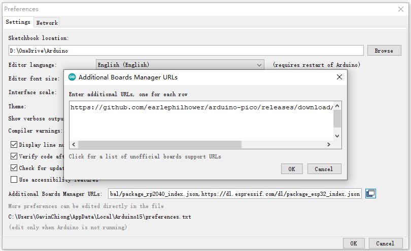
打開 Arduino IDE 并轉到“文件”->“首選項”。
在彈出的對話框中,在“Additional Boards Manager URLs”字段中輸入以下 URL:
https://github.com/earlephilhower/arduino-pico/releases/download/global/package_rp2040_index.json
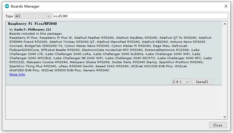
通過“Board Manager”搜索“WizFi360”并安裝 Board 支持
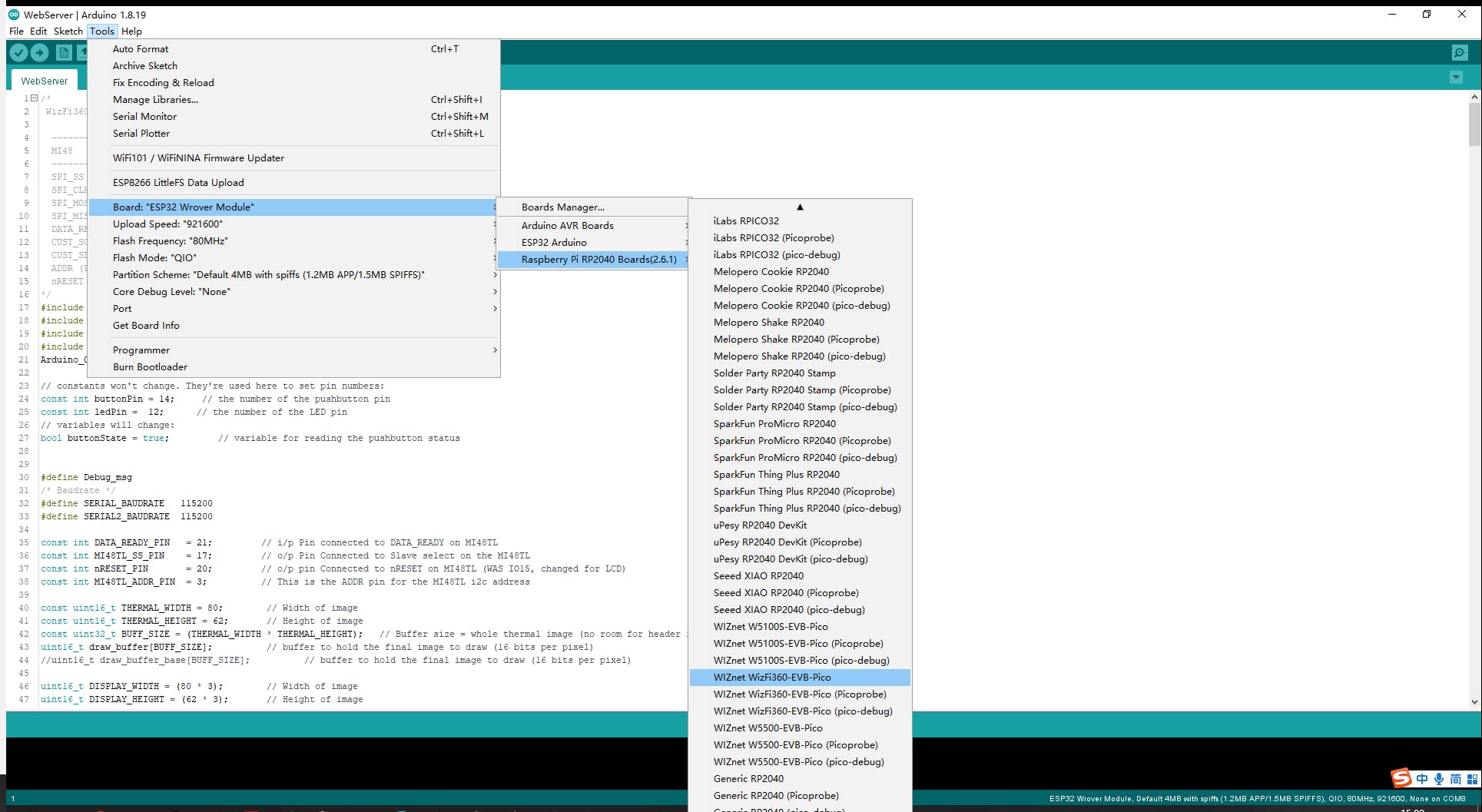
“工具->開發板:”***”-> Raspberry Pi RP2040 Boards(2.6.1)”選擇“WIZnet WizFi360-EVB-PICO”。
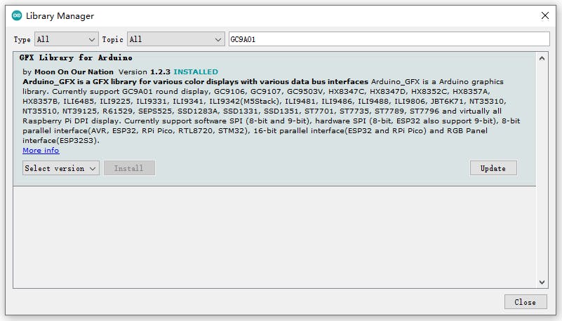
添加“GFX Library for rduino”,該庫支持圓屏GC9A01。
2. Thermography Carmera和協處理器初始化和數據處理
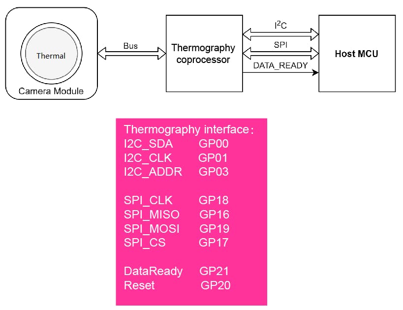
熱成像相機和協處理器接口和功能引腳初始化
#include                      // i2c library (standard Arduino library)
#include                       // SPI library (standard Arduino library)

const int THERMAL_DATA_READY_PIN   = 21;  //Pin connected to DATA_READY
const int THERMAL_CS_PIN           = 17;  //Pin Connected to CS
const int THERMAL_nRESET_PIN       = 20;  //pin Connected to nRESET
const int THERMAL_ADDR_PIN         = 3;   //The Thermography i2c address
uint16_t  THERMAL_Addr = 0x40;
/*i2c address for Thermography (0x40 if Thermography_ADDR_PIN =0 or 0x41 if Thermography_ADDR_PIN = 1 )*/
熱像注冊地址
// Now the addresses for each of the registers within the device
const uint16_t THERMAL_FRAME_MODE      = 0xB1; // Frame Mode register address
const uint16_t THERMAL_SW_VERSION      = 0xB2; // swVersion register address
const uint16_t THERMAL_BUILD           = 0xB3; // swVersion build register address
const uint16_t THERMAL_FRAME_RATE      = 0xB4; // Frame Rate register addres
const uint16_t THERMAL_POWER_DOWN      = 0xB5; // Power down register address
const uint16_t THERMAL_STATUS_ERROR    = 0xB6; // Status Error register address
const uint16_t THERMAL_SENSOR_TYPE     = 0xBA; // SenXor type register address
const uint16_t THERMAL_EMISSIVITY      = 0xCA; // emissivity register address
const uint16_t THERMAL_FILTER_CONTROL  = 0xD0; // filter control (bits 0-2 R_W)
const uint16_t THERMAL_FILTER_SETTINGS_LSB = 0xD1; // filter setting LSB (0x32 default, 0x80 rec)
const uint16_t THERMAL_FILTER_SETTINGS_MSB = 0xD2; // filter setting MSB (0x00 default)
const uint16_t THERMAL_ROLLING_AVG_SETTING = 0xD3; // rolling average setting (0x04 default)
I2C讀寫Thermography寄存器地址
// =========================================================================
//  Function to write i2c register
// =========================================================================
void WriteI2c(int RegAddr, unsigned char RegData)
{
  Wire.beginTransmission(Addr);       // Begin transmission to the Sensor
  Wire.write (RegAddr);                     // Set the address for the requested register
  Wire.write (RegData);                     // Write the data for that register
  Wire.endTransmission(true);               // Release i2c bus - so others can use it (can have multiple slaves & masters connected
  return;
}

// =========================================================================
//  Function to read i2c register
// =========================================================================
unsigned char ReadI2c(int RegAddr)
{
  unsigned char Result;
  Wire.beginTransmission(Addr);       // Begin transmission to the Sensor
  Wire.write (RegAddr);                     // Set the address for the requested register
  Wire.endTransmission();                   // End tranmission We should have set the address of the register
  Wire.requestFrom(Addr, 1);          // Tell slave we need to read 1 byte from the current register
  Result = Wire.read();                     // read that Serial Number byte (register will auto increment)
  Wire.endTransmission(true);               // Release i2c bus - so others can use it
  return Result;
}
在“void setup()”中通過I2C BUS獲取和設置參數
THERMAL_FILTER_CONTROL :將此位設置為 1 指示在連續捕獲模式下運行,從而連續從相機模塊獲取數據并更新可通過 SPI 接口訪問的讀出緩沖區。將此位重置為 0 指示停止連續數據采集。這也會將 DATA_READY 引腳和 STATUS 寄存器的相應位 4 重置為 0。
THERMAL_FRAME_RATE :這些位的值確定主機控制器可以通過 SPI 接口從輸出幀緩沖區讀取熱數據幀的速率。該值必須是一個無符號整數,表示所連接相機模塊的最大幀速率 FPS_MAX 的幀速率除數:FPS = FPS_MAX / FRAME_RATE_DIVIDER。例外情況是 FRAME_RATE = 0,這會產生 FPS_MAX = 24FPS。
THERMAL_FRAME_MODE :將此位設置為 1 會消除通過 SPI 接口傳輸的熱數據幀中的標頭。將此位重置為 0 包括熱數據幀中的 HEADER,
Wire.begin();                               // Initialise and configure the i2C//
  Wire.setClock(400000);                      // use 400 kHz I2C//

  pinMode(THERMAL_DATA_READY_PIN, INPUT_PULLUP);
  pinMode (nRESET_PIN, OUTPUT);
  digitalWrite (nRESET_PIN, LOW);              // First put the THERMAL in reset - THIS NEEDS TO BE TIMED//
  pinMode (THERMAL_ADDR_PIN, OUTPUT);
  digitalWrite (THERMAL_ADDR_PIN, LOW);        // Set the THERMAL i2c addrees LOW = 0x40 HIGH = 0x41//
  pinMode(THERMAL_CS_PIN, OUTPUT);             // Configure CS pin for THERMAL
  digitalWrite (THERMAL_CS_PIN, HIGH);
  delay(200);                      // Wait 0.2 seconds //
  digitalWrite (nRESET_PIN, HIGH); // remove reset to the THERMAL - allow it to boot//
  delay(1000);                     // Wait 1 seconds for the THERMAL to boot
  SPI.begin();                     // Initialise the SPI

  // =========================================================================
  //  Read all the individual i2c registers
  //  Uses ReadI2c() routine
  // =========================================================================
  frameMode = ReadI2c(THERMAL_FRAME_MODE);
  swVersion = ReadI2c(THERMAL_SW_VERSION);
  build     = ReadI2c(THERMAL_BUILD);
  frameRate = ReadI2c(THERMAL_FRAME_RATE);
  powerDown = ReadI2c(THERMAL_POWER_DOWN);
  statusError = ReadI2c(THERMAL_STATUS_ERROR);
  senxorType = ReadI2c(THERMAL_SENSOR_TYPE);
  emissivity = ReadI2c(THERMAL_EMISSIVITY);

  // =========================================================================
  // Write any registers required beofre starting exitig setup
  // and starting Data aquisition
  // =========================================================================
  WriteI2c(THERMAL_FILTER_SETTINGS_LSB, 0x80);
  WriteI2c(THERMAL_FILTER_SETTINGS_MSB, 0x00);
  WriteI2c(THERMAL_FILTER_CONTROL, 0x02);
  delay(100);         // currently required after modifying filter values//
  WriteI2c(THERMAL_FRAME_RATE, 0x3);           // Write the Frame_rate register 0x1 = as fast as possible (24FPS)//
  WriteI2c(THERMAL_FRAME_MODE, 0x3);           // Write the Frame_mode register 0x3 = capture continuous with header)//
在“void loop()”中通過SPI BUS獲取camera Header和data
SPI 時鐘設置為 40MHz,來自傳感器的數據相對于屏幕翻轉,因此我們必須向后繪制行。
void Get_sensor_data()
{
  dataReady = digitalRead(THERMAL_DATA_READY_PIN);
  // Read the state on THERMAL_DATA_READY_PIN line
  if ( digitalRead (THERMAL_DATA_READY_PIN) == HIGH) {
  // Wait for THERMAL_DATA_READY_PIN to assert
  Serial.println ("Data ready!!");
  //THERMAL_DATA_READY_PIN has been asserted so data is now available on SPI bus
  SPI.beginTransaction(SPISettings(40000000, MSBFIRST, SPI_MODE0));
  digitalWrite (THERMAL_CS_PIN, LOW);
  for (int i = 0; i < THERMAL_WIDTH; i++)
  {
    header_buffer[i] = SPI.transfer16(0x0);
    // write data to the header buffer
  }
  for (int j = 0; j < THERMAL_HEIGHT; j++)
  {
    for (int i = 0; i < THERMAL_WIDTH; i++)
    {
       THERMAL_SpiData = SPI.transfer16(0x0);
       // The data from the sensor is flipped with respect to the screen so we have to draw the rows backwards
       draw_buffer[((THERMAL_WIDTH - 1) - i) + (j * THERMAL_WIDTH)] = THERMAL_SpiData;
      }        // (finished a row)
    }
    // We have now read the entire frame of data
    digitalWrite (THERMAL_CS_PIN, HIGH);
    SPI.endTransaction();
  }
}
3. 在屏幕上顯示熱數據(GC9A01)。
#include
Arduino_GFX *tft = create_default_Arduino_GFX();
在“libraries\GFX_Library_for_Arduino\src\Arduino_GFX_Library.h”中定義 GC9A01 使用的引腳
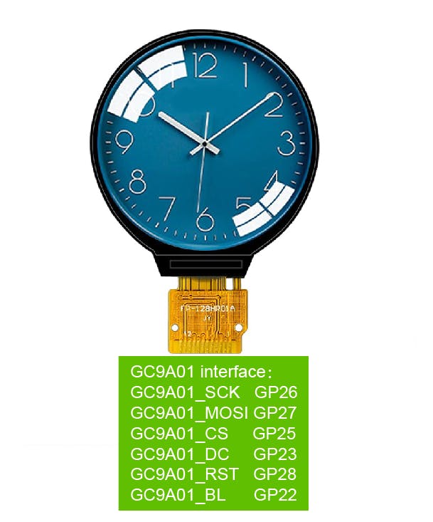
#elif defined(ARDUINO_RASPBERRY_PI_PICO)||defined(ARDUINO_WIZNET_WIZFI360_EVB_PICO)||defined(ARDUINO_WIZNET_5100S_EVB_PICO)
#define DF_GFX_SCK 26
#define DF_GFX_MOSI 27
#define DF_GFX_MISO GFX_NOT_DEFINED
#define DF_GFX_CS 25
#define DF_GFX_DC 23
#define DF_GFX_RST 28
#define DF_GFX_BL 22
在“void setup()”中初始化屏幕并打開屏幕的背光
tft->begin();
  tft->fillScreen(BLACK);
  pinMode(22, OUTPUT);
  digitalWrite(22, HIGH);
  Display_Begin();
將熱數據的每一個像素點轉化為顏色(RGB565),通過根據minmax中溫度值的相對位置(thermal Header中識別范圍內的溫度差)在colormap中找到對應的顏色信息。
通過“DISPLAY_buffer”函數顯示所有溫度顏色信息。由于攝像頭分辨率只有80*62,而GC9A01的屏幕分辨率為240*240,所以每個溫度點擴展為3*3顯示。
// =========================================================================
    // Colour conversion - one pixel at a time
    // The draw_buffer starts as 16 bit sensor data
    // At the end it is 16 bit RGB (5-6-5)
    // =========================================================================
    for (int j = 0; j < THERMAL_HEIGHT; j++) {
      for (int i = 0; i < THERMAL_WIDTH; i++) {
        pixelVal = draw_buffer[(i) + (j * THERMAL_WIDTH)];
        if (pixelVal <= THERMAL_MinVal) {
          lutIndex = 0;
        }
        else if (pixelVal >= THERMAL_MaxVal) {
          lutIndex = 255;
        }
        else {
          lutIndex = map (pixelVal, THERMAL_MinVal, THERMAL_MaxVal , 0, 0xff);
        }
        for(int m = 0; m<3; m++)
        {
            DISPLAY_buffer[(i*3)+m + (j*3) * DISPLAY_WIDTH]= palette[lutIndex];
            DISPLAY_buffer[(i*3)+m + ((j*3)+1) * DISPLAY_WIDTH]= palette[lutIndex];
            DISPLAY_buffer[(i*3)+m + ((j*3)+2) * DISPLAY_WIDTH]= palette[lutIndex];
        }
      }
    }
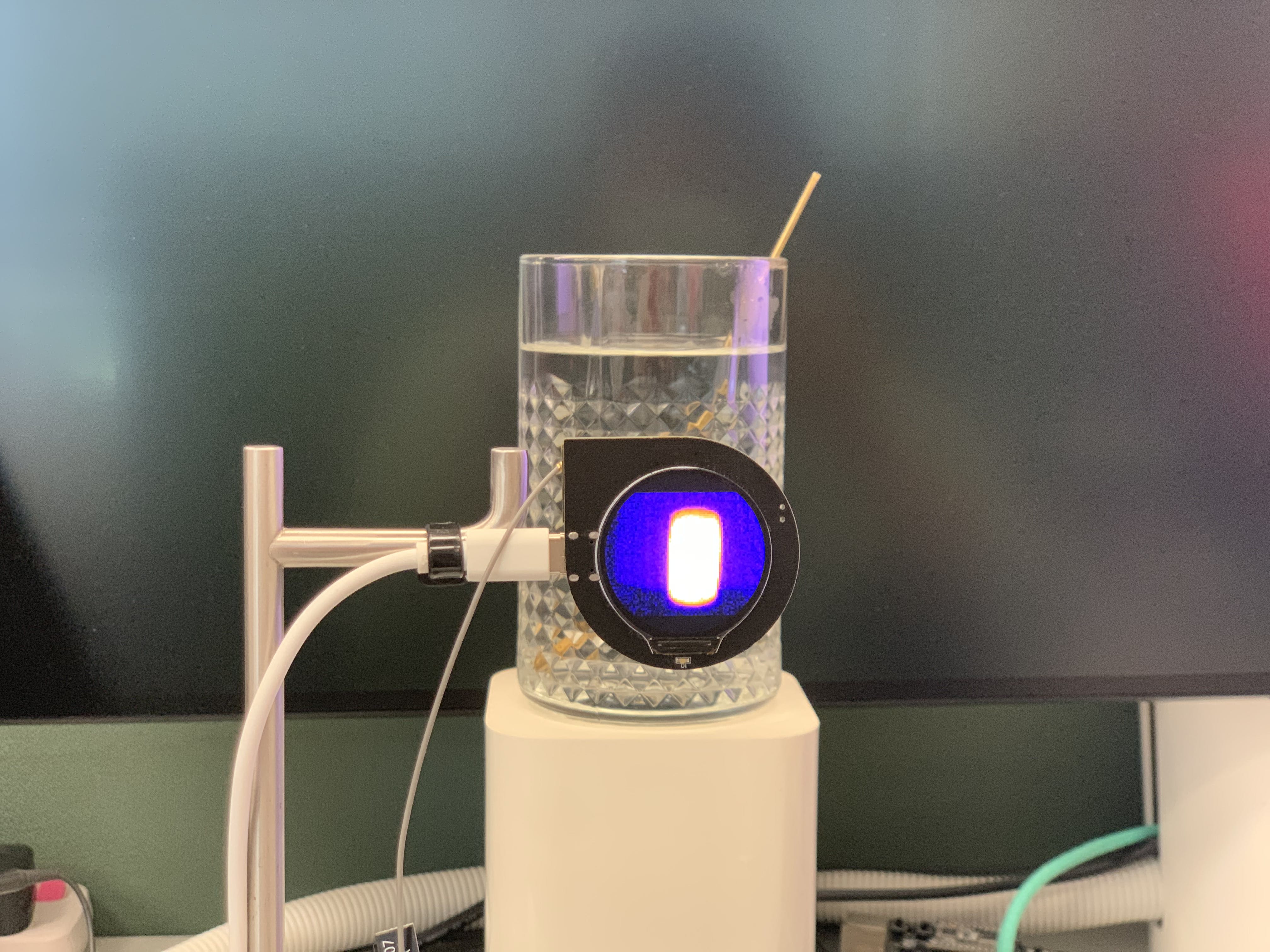
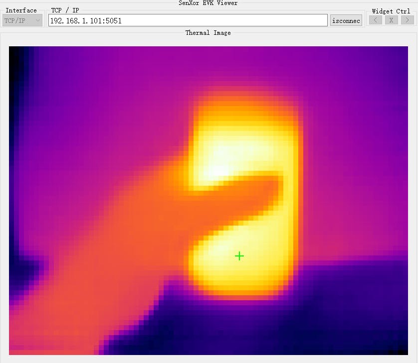
然后我們得到了這個項目中的第一張熱水熱成像圖。
4. WizFi360通過WiFi與熱查看器軟件通信。
Thermal Viewer 軟件作為 TCP 客戶端使用端口 5051。
#include "WizFi360.h"

// Wi-Fi info //
char ssid[] = "WIZNET_test";       // your network SSID (name)//
char pass[] = "********";          // your network password//
int status = WL_IDLE_STATUS;       // the Wifi radio's status//
WiFiServer server(5051);
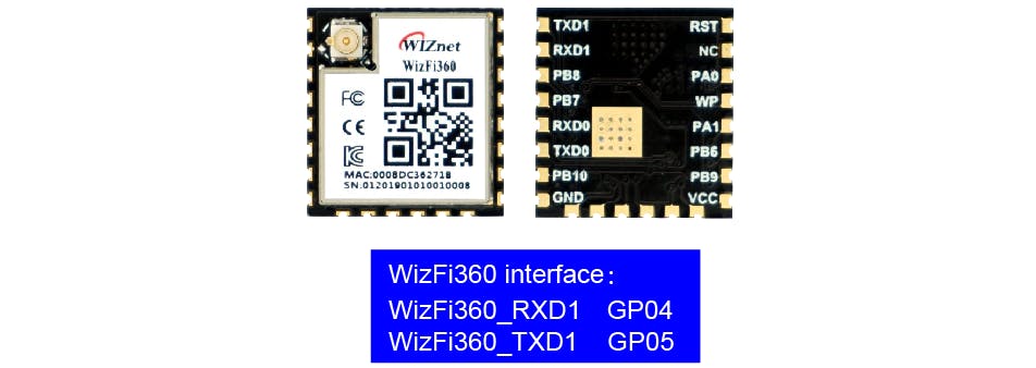
初始化WizFi360模塊的串口,修改波特率為2000000bps(wizfi360的最大波特率)。
第一次初始化為115200,然后在WiZfi360庫的初始化部分加入設置波特率(2000000),第二次改為2000000bps。
// initialize serial port for WizFi360 module//
#if defined(ARDUINO_WIZNET_WIZFI360_EVB_PICO)
  Serial2.begin(2000000);
  WiFi.init(&Serial2);
  Serial2.begin(2000000);
#endif
在“void setup()”中查看wifi的wizfi360 Link狀態
// check for the presence of the shield//
  if (WiFi.status() == WL_NO_SHIELD) {
    Serial.println("WiFi shield not present");
    // don't continue//
    while (true);
  }
  // attempt to connect to WiFi network//
  while ( status != WL_CONNECTED) {
    Serial.print("Attempting to connect to WPA SSID: ");
    Serial.println(ssid);
    // Connect to WPA/WPA2 network//
    status = WiFi.begin(ssid, pass);
  }
  Serial.println("You're connected to the network");
當熱查看器軟件連接到此服務器(WizFi360)時,RP2040 讀取熱數據“Get_sensor_data()”并將數據發布到 TCP 客戶端(熱查看器軟件)。
先傳熱像頭,再傳熱像素數據(80*62 16bits)。
WiFiClient client;
if (client) {
      Serial.println("Connected");
      socket_status = client.connected();
      socket_status_cnt = 0;
      delay(1000);
      uint8_t i;
      while (socket_status&&!buttonState)
      {
          switch(socket_send_status)
          {
            case 0:
            {
              Get_sensor_data();
              socket_send_result = client.write((uint8_t*)header_buffer,160);
              socket_send_status = 1;
            }break;
            case 1:
            {
              if(socket_send_result == 160 ){
                  socket_sendnum = 9920; //80*62*2//
                  socket_send_status = 2;
                  i=0;
              }else if(socket_send_result == 0){
                  socket_send_status = 4;
              }
            }break;
            case 2:
            {
              if(socket_sendnum >=2048)
              {
                socket_send_result = client.write((uint8_t*)(draw_buffer+(i*1024)),2048);
              }
              else
              {
                socket_send_result = client.write((uint8_t*)(draw_buffer+(i*1024)),socket_sendnum);
              }
              socket_send_status = 3;
            }break;
            case 3:
            {
               if(socket_sendnum >= 2048)
               {
                  if(socket_send_result == 2048)
                  {
                    socket_sendnum -= 2048;
                    i++;
                    socket_send_status = 2;
                  }else if(socket_send_result == 0){
                    socket_send_status = 4;
                  }
               }
               else
               {
                  if(socket_send_result == socket_sendnum)
                  {
                    socket_sendnum = 0;
                    socket_send_status = 4;
                   }
               }
            }break;
            case 4:
            {
                socket_status_cnt ++;
                if(socket_status_cnt == 20)
                {
                  socket_status = client.connected();
                  if(socket_status == 0)
                  {
                    client.stop();
                  }
                  socket_status_cnt = 0;
                }
                socket_send_status = 0;
            }break;
          }
     }
    }
Thermal viewer 軟件接收像素數據,它可以顯示和顯示這些像素的最高溫度。
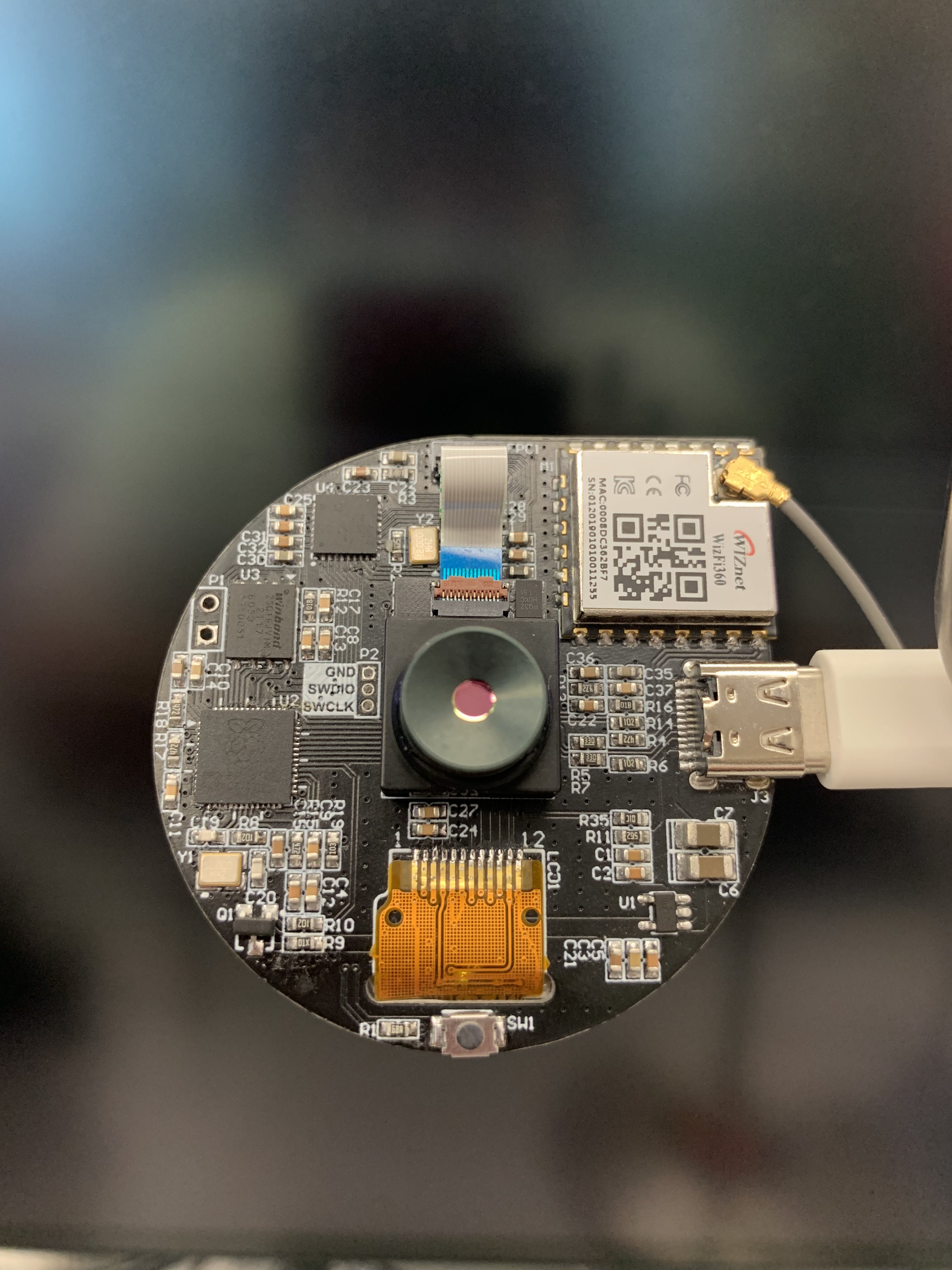
硬件如下圖
結束。
注意:由于簽署了保密協議,一些細節不能公開。
- 遠程編程Raspberry Pi Pico
- Raspberry Pi Pico上的ADC采樣和FFT
- Raspberry Pi Pico多功能入門套件
- 使用Wiznet Pico WizFi360和WS2812B LED制成的RGB天氣燈
- 將WizFi360 EVB Pico連接到Azure IoT Cloud
- WizFi360 EVB Mini脈搏血氧儀開源
- Raspberry Pi Pico作為HID鼠標
- 如何將WizFi360 EVB Mini添加到樹莓派Pico Python
- 使用Raspberry Pi Pico的LED序列
- Raspberry Pi Pico:使用PIO驅動伺服
- Grove UART WizFi360串行收發模塊
- 印有PINOUT的Raspberry Pi pico分線板
- 適用于Raspberry Pi 4的Raspberry Pi Pico開發板
- raspberry pi Pico使用MicroPython變磚后的解決方法
- 安防監控用熱成像儀 105次下載
- 5分鐘內將Raspberry Pi Pico變成簡單的示波器+波形發生器 1522次閱讀
- 使用RA6M5開發板的簡易熱成像儀設計 624次閱讀
- 紅外熱成像儀的基礎知識 2052次閱讀
- 使用Raspberry Pi Pico W和MicroPython開發物聯網應用 1673次閱讀
- Pico W的無線功能 883次閱讀
- 開源項目:基于小熊派STM32紅外熱成像儀 803次閱讀
- 使用Tis60+熱成像儀測量物體溫度和讀取溫度方法詳解 5638次閱讀
- DIY小熊派紅外熱成像儀 2478次閱讀
- 基于Raspberry Pi Pico的云端溫濕度監測站設計 1773次閱讀
- 基于樹莓派產品 Raspberry Pi微控制器板的優缺點 2710次閱讀
- 如何從Raspberry Pi Pico的模數轉換器捕獲數據計算? 2580次閱讀
- 基于Raspberry Pi Pico開發先進的家庭自動化系統 2849次閱讀
- 紅外熱成像儀在工業中的應用實例說明 9537次閱讀
- 紅外熱成像儀的工作原理、構成、特點分析 10.6w次閱讀
- 什么是紅外傳感器之紅外熱成像儀,紅外傳感器原理 2.3w次閱讀
下載排行
本周
- 1山景DSP芯片AP8248A2數據手冊
- 1.06 MB | 532次下載 | 免費
- 2RK3399完整板原理圖(支持平板,盒子VR)
- 3.28 MB | 339次下載 | 免費
- 3TC358743XBG評估板參考手冊
- 1.36 MB | 330次下載 | 免費
- 4DFM軟件使用教程
- 0.84 MB | 295次下載 | 免費
- 5元宇宙深度解析—未來的未來-風口還是泡沫
- 6.40 MB | 227次下載 | 免費
- 6迪文DGUS開發指南
- 31.67 MB | 194次下載 | 免費
- 7元宇宙底層硬件系列報告
- 13.42 MB | 182次下載 | 免費
- 8FP5207XR-G1中文應用手冊
- 1.09 MB | 178次下載 | 免費
本月
- 1OrCAD10.5下載OrCAD10.5中文版軟件
- 0.00 MB | 234315次下載 | 免費
- 2555集成電路應用800例(新編版)
- 0.00 MB | 33566次下載 | 免費
- 3接口電路圖大全
- 未知 | 30323次下載 | 免費
- 4開關電源設計實例指南
- 未知 | 21549次下載 | 免費
- 5電氣工程師手冊免費下載(新編第二版pdf電子書)
- 0.00 MB | 15349次下載 | 免費
- 6數字電路基礎pdf(下載)
- 未知 | 13750次下載 | 免費
- 7電子制作實例集錦 下載
- 未知 | 8113次下載 | 免費
- 8《LED驅動電路設計》 溫德爾著
- 0.00 MB | 6656次下載 | 免費
總榜
- 1matlab軟件下載入口
- 未知 | 935054次下載 | 免費
- 2protel99se軟件下載(可英文版轉中文版)
- 78.1 MB | 537798次下載 | 免費
- 3MATLAB 7.1 下載 (含軟件介紹)
- 未知 | 420027次下載 | 免費
- 4OrCAD10.5下載OrCAD10.5中文版軟件
- 0.00 MB | 234315次下載 | 免費
- 5Altium DXP2002下載入口
- 未知 | 233046次下載 | 免費
- 6電路仿真軟件multisim 10.0免費下載
- 340992 | 191187次下載 | 免費
- 7十天學會AVR單片機與C語言視頻教程 下載
- 158M | 183279次下載 | 免費
- 8proe5.0野火版下載(中文版免費下載)
- 未知 | 138040次下載 | 免費
 電子發燒友App


 創作
創作 發文章
發文章 發帖
發帖  提問
提問  發資料
發資料 發視頻
發視頻 上傳資料賺積分


評論