Many products that connect to phone lines (modems, for instance) incorporate a "call-progress monitoring" function known as CPM. CPM circuits "listen" to the lines as a human would, and respond according to what they "hear." You shouldn't dial a number unless you first hear a dial tone, for example. Neither should your computer.
Tone accuracy is not very important when people monitor the call-progress tones, but the use of computers for this purpose has produced a need for tone-accuracy specifications to prevent errors in interpretation. Accordingly, CCITT has introduced the North American Precise Audible Tone Plan (the following data is from the CCITT Green Book, Volume VI-4):
Figure 1 illustrates a simple circuit for generating single or dual tones. They must be ±0.5% accurate in frequency, and they must be gated as shown in the "Cadence" column (a μP can control the cadence). This generator suits applications such as the tone-generation portion of a test stimulus for CPM circuits.
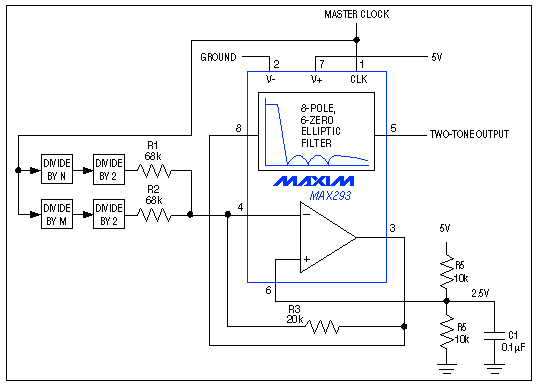
Figure 1. In this tone generator, the uncommitted op amp of the lowpass filter IC1 acts as a summing amplifier. The amplifier's gain level assures that 5V-logic inputs will not cause clipping at the two-tone output.
Generating a sine wave is generally more difficult than generating a square wave of the same frequency. The simplest technique is to filter a square wave of the desired frequency; removing its harmonics leaves you with the fundamental sine wave—the desired signal. For a dual-tone generator you would seem to need two harmonic-removal filters, but a single filter will do if the two square waves are reasonably close in frequency.
Square waves contain only odd harmonics, so the lowest frequency component to be removed (the critical frequency) is the third harmonic of the lower-frequency square wave. The filter must pass the fundamental of the higher-frequency square wave. To avoid using two filters, each of these square-wave frequencies must be an even-integer divisor of the filter's switched-capacitor clock. (This requirement forces the signal to be square-i.e., with a 50% duty cycle.)
As another requirement, the ratio of the lower tone's 3rd harmonic to the filter's corner frequency must be greater than the filter's transition ratio. (Transition ratio is the edge of the stopband divided by the edge of the passband.) The parameters necessary for generating each tone pair (or tone) are summarized in the table below.

The switched-capacitor lowpass filter (IC1), with a transition ratio of 1.5 and a clock-to-corner ratio of 100, meets each of these four sets of requirements. Setting the cutoff frequency to 528Hz, for example, allows 440Hz and 480Hz to pass. The resulting 792Hz stopband (528Hz times the 1.5 transition ratio) blocks the critical third harmonic of 440Hz (1320Hz), enabling generation of the ringing signal.
To generate low and high tones for the ringing signal, divide 52.8kHz by the divisors 120 and 110. The division scheme (left to the reader) can be implemented with simple logic, a PAL, or an up-counter/timer chip. If you use a programmable divider, you should follow it with a divide-by-two circuit to assure a 50% duty cycle. (The other CPM signals are produced in a similar way.)
Dual tones for the ringing signal are illustrated in the time domain (Figure 2) and the frequency domain (Figure 3). The frequency domain shows that the generator is free of spurious tones. In some CPM applications, tone detection involves a combination of frequency verification and guard margin. By verifying that tone energy is sufficiently above the remaining spectral energy, the tone margin ensures that voice and other signals won't fool the system into thinking a CPM tone is present.
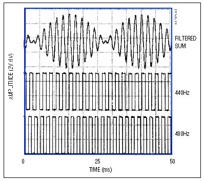
Figure 2. These time-domain waveforms show the low and high square-wave tones for the "ringing" signal (lower traces), and the sinusoidal filtered sum (top trace).
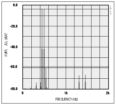
Figure 3. In this frequency spectrum of the top trace in Figure 1, the highest-amplitude spur (spurious frequency) is at least 54dB down from the twin-tone level.
Tone accuracy is not very important when people monitor the call-progress tones, but the use of computers for this purpose has produced a need for tone-accuracy specifications to prevent errors in interpretation. Accordingly, CCITT has introduced the North American Precise Audible Tone Plan (the following data is from the CCITT Green Book, Volume VI-4):
|
|
|
(per tone, at exchange) |
| |||
|
|
|
|
| |||
|
|
 |
 |
|
| ||
|
|
 |
 |
|
0.5sec off | ||
|
|
 |
 |
|
0.3sec off; or 0.3sec on; 0.2sec off | ||
|
|
 |
 |
|
4sec off | ||
|
|
 |
|
every 10sec | |||
Figure 1 illustrates a simple circuit for generating single or dual tones. They must be ±0.5% accurate in frequency, and they must be gated as shown in the "Cadence" column (a μP can control the cadence). This generator suits applications such as the tone-generation portion of a test stimulus for CPM circuits.

Figure 1. In this tone generator, the uncommitted op amp of the lowpass filter IC1 acts as a summing amplifier. The amplifier's gain level assures that 5V-logic inputs will not cause clipping at the two-tone output.
Generating a sine wave is generally more difficult than generating a square wave of the same frequency. The simplest technique is to filter a square wave of the desired frequency; removing its harmonics leaves you with the fundamental sine wave—the desired signal. For a dual-tone generator you would seem to need two harmonic-removal filters, but a single filter will do if the two square waves are reasonably close in frequency.
Square waves contain only odd harmonics, so the lowest frequency component to be removed (the critical frequency) is the third harmonic of the lower-frequency square wave. The filter must pass the fundamental of the higher-frequency square wave. To avoid using two filters, each of these square-wave frequencies must be an even-integer divisor of the filter's switched-capacitor clock. (This requirement forces the signal to be square-i.e., with a 50% duty cycle.)
As another requirement, the ratio of the lower tone's 3rd harmonic to the filter's corner frequency must be greater than the filter's transition ratio. (Transition ratio is the edge of the stopband divided by the edge of the passband.) The parameters necessary for generating each tone pair (or tone) are summarized in the table below.

The switched-capacitor lowpass filter (IC1), with a transition ratio of 1.5 and a clock-to-corner ratio of 100, meets each of these four sets of requirements. Setting the cutoff frequency to 528Hz, for example, allows 440Hz and 480Hz to pass. The resulting 792Hz stopband (528Hz times the 1.5 transition ratio) blocks the critical third harmonic of 440Hz (1320Hz), enabling generation of the ringing signal.
To generate low and high tones for the ringing signal, divide 52.8kHz by the divisors 120 and 110. The division scheme (left to the reader) can be implemented with simple logic, a PAL, or an up-counter/timer chip. If you use a programmable divider, you should follow it with a divide-by-two circuit to assure a 50% duty cycle. (The other CPM signals are produced in a similar way.)
Dual tones for the ringing signal are illustrated in the time domain (Figure 2) and the frequency domain (Figure 3). The frequency domain shows that the generator is free of spurious tones. In some CPM applications, tone detection involves a combination of frequency verification and guard margin. By verifying that tone energy is sufficiently above the remaining spectral energy, the tone margin ensures that voice and other signals won't fool the system into thinking a CPM tone is present.

Figure 2. These time-domain waveforms show the low and high square-wave tones for the "ringing" signal (lower traces), and the sinusoidal filtered sum (top trace).

Figure 3. In this frequency spectrum of the top trace in Figure 1, the highest-amplitude spur (spurious frequency) is at least 54dB down from the twin-tone level.
 電子發燒友App




評論