Switched-capacitor filters (SCFs) are renowned for ease of use. They are accurate, require no external components, and maintain a predictable response over all specified operating conditions. For integrated-circuit SCFs, their tightly matched and trimmed internal capacitors produce a fixed frequency and phase response that is proportional solely to the external clock frequency.
To construct a notch (band-reject) or passband response, the more flexible universal filter is needed. Universal filters (either SCF or continuous-time types) allow any combination of low-pass, high-pass, bandpass, or band-reject response, but they cost $3 to $10 each (1k pcs) and come in 14- to 16-pin DIPs or large surface-mount packages. They usually require a dual-voltage power supply.
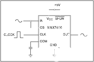
The low-pass SC filter of Figure 1, on the other hand, has features that enable a notch-filter configuration. This fifth-order Butterworth low-pass filter operates on a single supply, has rail-to-rail I/O, fits in a tiny 8-pin μMAX? package half the size of an 8-pin SO, and costs less than $1.50. Its internal architecture (Figure 2) has summing nodes similar to those used for feedback-error generation in analog signal-processing stages. When operating, it low-pass-filters the quantity (VIN - VCOM) and adds VOS at the output:
VOUT = (VIN-VCOM) LPF + VOS,
where (typically) VCOM = VDD/2.
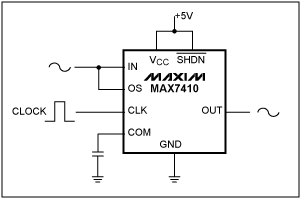
Figure 1. These simple connections produce a band-reject (notch) filter response.

Figure 2. Summing nodes internal to the IC (Figure 1) add a VDD/2 common-mode voltage and an externally applied offset voltage.
Thus, the device adds common-mode voltage (COM) at the input, biased at mid-supply by an internal resistor divider, and (for applications that require offset adjustment or DC-level shifting) adds an external bias voltage (OS) at the output.
To obtain a notch response, the input signal in Figure 1 is applied to OS as well as the input, so these two signals are summed together at the output. Frequencies at OS are limited to approximately 100kHz. At low frequencies, the output amplitude equals | VIN + VOS |= 2 | VIN |. At the frequency for which the LPF phase response changes 180°, the two signals sum to near zero, creating the notch frequency. (Notch frequencies from 1Hz to 10kHz are easily attainable.) At higher frequencies, only the OS signal passes through to the output.
Figure 3a shows the filter response for a 400Hz notch and a clock frequency of 47.5kHz. The Q is 1.7, and the center-frequency attenuation is approximately -50dB.
Ripple in the passband limits the notch depth, so IC1's flat passband in the low-pass configuration suits this application. The 180° shift occurs at 0.85fC, giving the response a smooth -6dB transition between the pre-notch and post-notch frequencies (Figure 3b). The usable input bandwidth is (fCLK-fCLK/100), thanks to a 100:1 ratio between the fC and clock frequencies. As with all sampling systems, care must be taken to avoid input-signal aliasing.
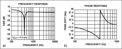
Figure 3. Applying a 47.5kHz clock frequency to the circuit of Figure 1 produces a 400Hz notch filter with (a) notch depth of 50dB and (b) Q of 1.7.
A similar version of this article appeared in the September 30, 1999 issue of EDN.
To construct a notch (band-reject) or passband response, the more flexible universal filter is needed. Universal filters (either SCF or continuous-time types) allow any combination of low-pass, high-pass, bandpass, or band-reject response, but they cost $3 to $10 each (1k pcs) and come in 14- to 16-pin DIPs or large surface-mount packages. They usually require a dual-voltage power supply.
The low-pass SC filter of Figure 1, on the other hand, has features that enable a notch-filter configuration. This fifth-order Butterworth low-pass filter operates on a single supply, has rail-to-rail I/O, fits in a tiny 8-pin μMAX? package half the size of an 8-pin SO, and costs less than $1.50. Its internal architecture (Figure 2) has summing nodes similar to those used for feedback-error generation in analog signal-processing stages. When operating, it low-pass-filters the quantity (VIN - VCOM) and adds VOS at the output:

Figure 1. These simple connections produce a band-reject (notch) filter response.

Figure 2. Summing nodes internal to the IC (Figure 1) add a VDD/2 common-mode voltage and an externally applied offset voltage.
Thus, the device adds common-mode voltage (COM) at the input, biased at mid-supply by an internal resistor divider, and (for applications that require offset adjustment or DC-level shifting) adds an external bias voltage (OS) at the output.
To obtain a notch response, the input signal in Figure 1 is applied to OS as well as the input, so these two signals are summed together at the output. Frequencies at OS are limited to approximately 100kHz. At low frequencies, the output amplitude equals | VIN + VOS |= 2 | VIN |. At the frequency for which the LPF phase response changes 180°, the two signals sum to near zero, creating the notch frequency. (Notch frequencies from 1Hz to 10kHz are easily attainable.) At higher frequencies, only the OS signal passes through to the output.
Figure 3a shows the filter response for a 400Hz notch and a clock frequency of 47.5kHz. The Q is 1.7, and the center-frequency attenuation is approximately -50dB.
Ripple in the passband limits the notch depth, so IC1's flat passband in the low-pass configuration suits this application. The 180° shift occurs at 0.85fC, giving the response a smooth -6dB transition between the pre-notch and post-notch frequencies (Figure 3b). The usable input bandwidth is (fCLK-fCLK/100), thanks to a 100:1 ratio between the fC and clock frequencies. As with all sampling systems, care must be taken to avoid input-signal aliasing.

Figure 3. Applying a 47.5kHz clock frequency to the circuit of Figure 1 produces a 400Hz notch filter with (a) notch depth of 50dB and (b) Q of 1.7.
A similar version of this article appeared in the September 30, 1999 issue of EDN.
μMAX is a registered trademark of Maxim Integrated Products, Inc.
 電子發燒友App





評論