Abstract: An unorthodox application of a pair of MOSFET-driver ICs and a ferrite-bead transformer yields a single-channel, isolated digital-signal coupler.
Optocouplers are the usual choice for coupling digital signals between isolated circuits with different ground levels. Optocouplers have disadvantages, however. Their most important parameters, current transfer and propagation time, change with aging. They have a relatively high static power consumption and, for most types, limited speed.
Figure 1 is an alternative to optocoupler designs. This unorthodox approach offers very low I/O capacitance (less than 0.5pF), a static power consumption of zero, a propagation time of approximately 10ns, and a pulse-width transmission capability ranging from 30ns to DC. This magnetic-coupled circuit takes advantage of both the logic structures at the inputs of the two MOSFET driver ICs (MAX5048A), and the fast, matched propagation times of those ICs.
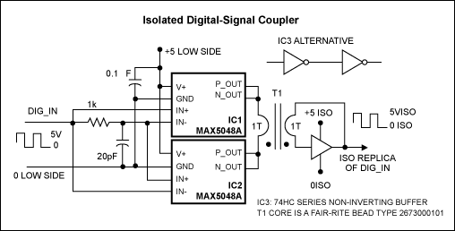
Figure 1. This magnetic-coupled circuit for digital signals is an alternative to optocoupler designs.
Besides the 10ns propagation time of the MAX5048 driver, an additional 10ns of propagation time is present due to the high-side flip-flop gate. That 10ns can be reduced by using faster logic. The breakdown voltage of the I/O insulation barrier depends only on the insulation of the ferrite bead transformer used as the magnetic coupler and board construction. That voltage, moreover, can be elevated to several kV by changing the wire insulation used in the single-turn magnetic coupler.
The magnetic coupler is a ferrite-bead (3.5mm OD, 1.3mm ID, and 3.25mm height) transformer with two windings of a single turn each. The I/O capacitance is very small (about 0.3 pF), and once again, depends only on the transformer, board design, and construction.
The scope photos show propagation delays for a negative 50ns input pulse (Figure 2), and a positive 50ns input pulse (Figure 3), along with the associated input and output signals.
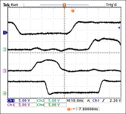
Figure 2. These waveforms show the propagation delay (about 25ns) for a negative-pulse input to the circuit in Figure 1.
Channel 1 = Input Signal
Channel 2 = Side A Coil Driver
Channel 3 = Side B Coil Driver
Channel 4 = Output of Gate Flip Flop
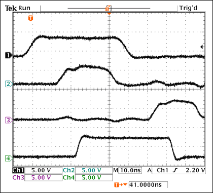
Figure 3. These waveforms show the propagation delay (also about 25ns) for a positive-pulse input to the circuit in Figure 1.
Channel 1 = Input Signal
Channel 2 = Side A Coil Driver
Channel 3 = Side B Coil Driver
Channel 4 = Output of Gate Flip Flop
Unlike optocoupler circuits, the initial output state from the magnetic-coupler design is not determined until the first input-signal transition of either polarity occurs. Thereafter, the isolated output follows the input states. Input-signal rise and fall times must be fast (<10ns).
A similar article appeared in the Planet Analog section of the April 11, 2005 edition of EE Times.
Optocouplers are the usual choice for coupling digital signals between isolated circuits with different ground levels. Optocouplers have disadvantages, however. Their most important parameters, current transfer and propagation time, change with aging. They have a relatively high static power consumption and, for most types, limited speed.
Figure 1 is an alternative to optocoupler designs. This unorthodox approach offers very low I/O capacitance (less than 0.5pF), a static power consumption of zero, a propagation time of approximately 10ns, and a pulse-width transmission capability ranging from 30ns to DC. This magnetic-coupled circuit takes advantage of both the logic structures at the inputs of the two MOSFET driver ICs (MAX5048A), and the fast, matched propagation times of those ICs.

Figure 1. This magnetic-coupled circuit for digital signals is an alternative to optocoupler designs.
Besides the 10ns propagation time of the MAX5048 driver, an additional 10ns of propagation time is present due to the high-side flip-flop gate. That 10ns can be reduced by using faster logic. The breakdown voltage of the I/O insulation barrier depends only on the insulation of the ferrite bead transformer used as the magnetic coupler and board construction. That voltage, moreover, can be elevated to several kV by changing the wire insulation used in the single-turn magnetic coupler.
The magnetic coupler is a ferrite-bead (3.5mm OD, 1.3mm ID, and 3.25mm height) transformer with two windings of a single turn each. The I/O capacitance is very small (about 0.3 pF), and once again, depends only on the transformer, board design, and construction.
The scope photos show propagation delays for a negative 50ns input pulse (Figure 2), and a positive 50ns input pulse (Figure 3), along with the associated input and output signals.

Figure 2. These waveforms show the propagation delay (about 25ns) for a negative-pulse input to the circuit in Figure 1.
Channel 1 = Input Signal
Channel 2 = Side A Coil Driver
Channel 3 = Side B Coil Driver
Channel 4 = Output of Gate Flip Flop

Figure 3. These waveforms show the propagation delay (also about 25ns) for a positive-pulse input to the circuit in Figure 1.
Channel 1 = Input Signal
Channel 2 = Side A Coil Driver
Channel 3 = Side B Coil Driver
Channel 4 = Output of Gate Flip Flop
Unlike optocoupler circuits, the initial output state from the magnetic-coupler design is not determined until the first input-signal transition of either polarity occurs. Thereafter, the isolated output follows the input states. Input-signal rise and fall times must be fast (<10ns).
A similar article appeared in the Planet Analog section of the April 11, 2005 edition of EE Times.
 電子發燒友App





評論