Abstract: Multichannel analog-to-digital converters (ADCs) typically convert each input channel sequentially using an input multiplexer. Certain applications require simultaneous conversions, especially when phase information exists between different channels. For example, wireless applications require I and Q channels to be converted at the same instance, motor control and power monitoring requires voltage and current measurements and the phase angle between them. In the past, simultaneous sampling meant the designer had to use multiple ADCs, and perform parallel conversions on each channel. Simultaneous sampling ADCs now perform the task using multiple T/H to sample the inputs at the same instant, then perform the conversion for each channel.
The introduction of high-speed 14-bit simultaneous-sampling A/D converters has widened the range of applications for which accurate phase measurement among two or more waveforms is feasible economically. In the following discussion, two such ADCs are used to illustrate the major applications of this type.
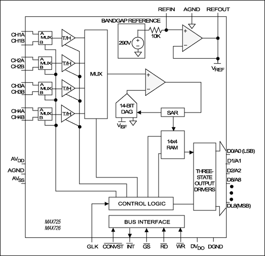
The MAX125 and the MAX126 are complete 14-bit data-acquisition systems in which four of eight inputs are tracked and held simultaneously (Figure 1). An on-board sequencer allows the user to program which four (or fewer) channels are to be digitized. Throughput rates range from 250ksps for one channel to 76ksps for all four channels. The input ranges are ±5V (MAX125) and ±2.5V (MAX126).
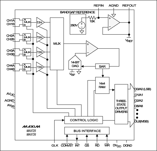
Figure 1. This 14-bit successive-approximation A/D converter can sample four of eight input channels simultaneously.
Each of the four track/hold (T/H) stages can switch between an "A" and a "B" input, yielding a total of eight possible input channels (Figure 2). The diagram shows channel A in the track mode. A T-switch at each T/H input minimizes the crosstalk between adjacent channels. Four address pins select the number of channels and the operating mode, and each input circuit tolerates overvoltages to ±17V. The chip also includes a voltage reference with a typical drift of 30ppm/°C.
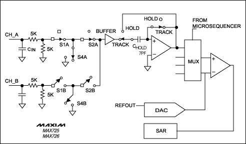
Figure 2. An equivalent circuit demonstrates that the input of each track/hold in Figure 1 can be switched to one of two input channels.
Thus, by decoupling a motor's field and torque components and controlling them directly, field orientation provides the motor with a fast and accurate dynamic response. To vary the motor torque, one needs to modify the rotor current component that is responsible for generating torque (Iq), while maintaining the field (or magnetizing) current component (Id) constant. Looking at Figure 3, we can see that the magnetizing current is
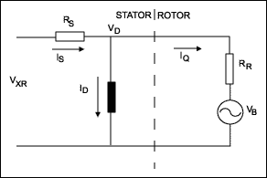
Figure 3. Simultaneous sampling monitors the voltages and currents in an induction motor. This equivalent circuit shows one phase of the motor.
Field-oriented control (FOC) is classified as direct, indirect, or sensorless. Direct FOC measures the rotor angle directly, with sensors located in the motor housing. Indirect FOC measures the speed, for instance, using resolvers, and then determines the slip angle1 by integrating the speed. Rotor angular frequency added to slip frequency gives the required stator frequency. Frequency is therefore a byproduct of this control technique rather than the controlling variable.
Sensorless FOC is the focus of much attention, especially for applications in which signal feedback directly from the rotor is unfeasible. These include the underwater pumps found in offshore oilrigs and other systems for which the motor and drive electronics are far apart physically. Unlike direct and indirect FOC, sensorless FOC performs all measurements and calculations on the stator side of the motor (Figure 4).
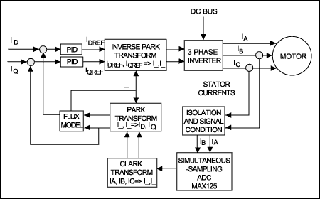
Figure 4. This simplified block diagram illustrates sensorless field-oriented motor control.
Considering Figure 4 and the vector diagram (Figure 5), you can see that the MAX125 digitizes two stator phase currents (ib and ic). Note that only two phase currents are required, as the third one (ia) can be derived from the assumption that the three phase currents are 120 electrical degrees apart and instantaneously add to zero. The three currents are then converted to a two-phase orthogonal system with axes α and β by means of a technique called the Clarke Transformation.
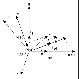
Figure 5. This vector diagram depicts the coordinate transformations necessary in field-oriented control (FOC).
For simplicity, axis α can be made equal to axis a. The two orthogonal currents iα and iβ are then transformed to a time-invariant, rotating orthogonal system represented by the field and torque components d and q of the equivalent rotor currents id and iq. The α / β coordinate frame is rotated counterclockwise to line up with the rotor flux axis ψr. The angle of rotation (θ) is determined with the aid of the motor model; this is a rotation of coordinates called the Park Transformation.
This last transformation greatly reduces system complexity by expressing the currents as dc quantities. Combining the rotor flux angle (θ) with currents obtained from the Park Transformation lets you obtain the actual motor field and torque. By allowing a comparison of reference torque and measured torque, the Park Transformation plays a major role in the control loop. After you obtain the desired torque and flux, an Inverse Park Transformation translates the reference torque and field currents (idref, iqref) back, first to the orthogonal stator-frame currents ( iα, iβ) and then to their respective three-phase instantaneous stator currents (ia, ib, and ic). All transformations are carried out by a DSP. The real-time execution of control and input commands is handled by a microprocessor.
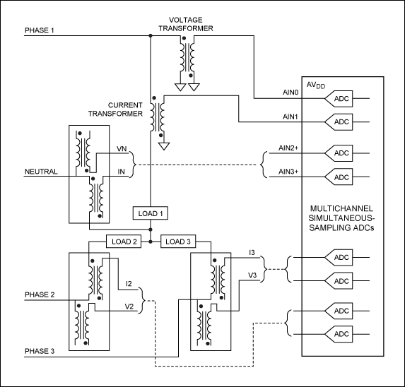
Another application requiring the use of simultaneous-sampling ADCs is the measurement of high-voltage three-phase waveforms in line-fault protection systems (Figure 6). The slow-changing 50Hz to 60Hz signals to be measured allow the use of multiple delta-sigma converters, which offer very high resolution while obviating the need for anti-aliasing filters. Although single sigma-delta ADCs are low in cost, the seven channels typically required in this application (for three voltages and four currents) increase the converter cost roughly four times with respect to a single MAX125.

Figure 6. This simplified diagram shows the major blocks in a line-fault protector.
A third application for the MAX125 can be found in Coriolis-based mass-flow meters (Figure 7). The Coriolis principle is based on exciting a section of pipe with a low-frequency vibration and picking up the resulting pipe deformations caused by the mass flowing through it. The source of excitation is typically a vibrating coil, and the resulting deflection is picked up by a voice coil. These deflections can also be picked up by optical means.
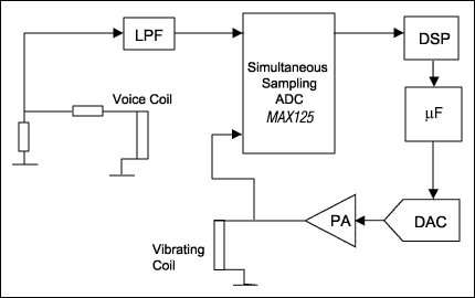
Figure 7. This simplified block diagram shows a typical Coriolis-based mass-flow meter.
When comparing the excitation and pickup signals, these deflections appear as a phase difference that can be detected using simultaneous sampling. Although the signal frequency is relatively low (50Hz to 500Hz typical), detection of the very small phase shifts requires a high-speed high-resolution simultaneous-sampling ADC.
In the high-frequency arena, one also encounters simultaneous sampling for digitizing I and Q signals obtained from, say, a direct downconversion satellite tuner IC. Commercial satellite-receiver systems, for instance, employ a dual 6-bit high-speed (60MHz to 90MHz) simultaneous-sampling ADC especially designed for the application (Figure 8).
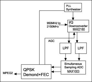
Figure 8. A commercial satellite-receiver system employs simultaneous sampling of the I and Q signals.
Simultaneous sampling at similar speeds can eliminate the intermediate-frequency stage in collision-warning and adaptive-cruise-control automotive systems. This approach, however, requires rather expensive flash ADCs with 8-bits to 10-bits of resolution. By using undersampling techniques, similar results can be achieved below 1Msps. Shipboard radar detection also requires simultaneous sampling, at between 10Msps and 30Msps with 12-bit resolution. This function can be performed with two ADCs (MAX1172) whose trimmable reference inputs enable the compensation of system gain and offset.
1In AC asynchronous motors, a rotating field is induced in the rotor, which causes it to rotate in the same direction of the stator field but at a slower angular frequency. The difference in these frequencies is called "slip frequency" and the angle between them the "slip angle." A similar article appeared in the June 2000 issue of Sensors.
The introduction of high-speed 14-bit simultaneous-sampling A/D converters has widened the range of applications for which accurate phase measurement among two or more waveforms is feasible economically. In the following discussion, two such ADCs are used to illustrate the major applications of this type.
The MAX125 and the MAX126 are complete 14-bit data-acquisition systems in which four of eight inputs are tracked and held simultaneously (Figure 1). An on-board sequencer allows the user to program which four (or fewer) channels are to be digitized. Throughput rates range from 250ksps for one channel to 76ksps for all four channels. The input ranges are ±5V (MAX125) and ±2.5V (MAX126).

Figure 1. This 14-bit successive-approximation A/D converter can sample four of eight input channels simultaneously.
Each of the four track/hold (T/H) stages can switch between an "A" and a "B" input, yielding a total of eight possible input channels (Figure 2). The diagram shows channel A in the track mode. A T-switch at each T/H input minimizes the crosstalk between adjacent channels. Four address pins select the number of channels and the operating mode, and each input circuit tolerates overvoltages to ±17V. The chip also includes a voltage reference with a typical drift of 30ppm/°C.

Figure 2. An equivalent circuit demonstrates that the input of each track/hold in Figure 1 can be switched to one of two input channels.
Applications
Field-oriented (vector) controls, which enable AC motors to behave like DC motors, constitute a major application for which MAX125/MAX126 converters are intended. The brush and commutator assembly in a dc motor ensures that the field (stator) current is always at right angles to the armature (rotor) current. Known as field orientation, this condition allows the rotor to generate the maximum torque for which it is rated.Thus, by decoupling a motor's field and torque components and controlling them directly, field orientation provides the motor with a fast and accurate dynamic response. To vary the motor torque, one needs to modify the rotor current component that is responsible for generating torque (Iq), while maintaining the field (or magnetizing) current component (Id) constant. Looking at Figure 3, we can see that the magnetizing current is
Id = Vd/jωLm,where ω is the angular frequency of the applied voltage and Lm is the rotor's magnetizing inductance. Thus, holding the Vd/ω ratio constant lets you maintain a constant torque at various speeds. On the other hand, you can control speed by varying the stator voltage, Vd. This voltage cannot be measured directly, but it can be inferred from knowledge of the input voltage VxR, the stator current, and the stator resistance at various temperatures (i.e., Vd = VxR - IsRs).

Figure 3. Simultaneous sampling monitors the voltages and currents in an induction motor. This equivalent circuit shows one phase of the motor.
Field-oriented control (FOC) is classified as direct, indirect, or sensorless. Direct FOC measures the rotor angle directly, with sensors located in the motor housing. Indirect FOC measures the speed, for instance, using resolvers, and then determines the slip angle1 by integrating the speed. Rotor angular frequency added to slip frequency gives the required stator frequency. Frequency is therefore a byproduct of this control technique rather than the controlling variable.
Sensorless FOC is the focus of much attention, especially for applications in which signal feedback directly from the rotor is unfeasible. These include the underwater pumps found in offshore oilrigs and other systems for which the motor and drive electronics are far apart physically. Unlike direct and indirect FOC, sensorless FOC performs all measurements and calculations on the stator side of the motor (Figure 4).

Figure 4. This simplified block diagram illustrates sensorless field-oriented motor control.
Considering Figure 4 and the vector diagram (Figure 5), you can see that the MAX125 digitizes two stator phase currents (ib and ic). Note that only two phase currents are required, as the third one (ia) can be derived from the assumption that the three phase currents are 120 electrical degrees apart and instantaneously add to zero. The three currents are then converted to a two-phase orthogonal system with axes α and β by means of a technique called the Clarke Transformation.

Figure 5. This vector diagram depicts the coordinate transformations necessary in field-oriented control (FOC).
For simplicity, axis α can be made equal to axis a. The two orthogonal currents iα and iβ are then transformed to a time-invariant, rotating orthogonal system represented by the field and torque components d and q of the equivalent rotor currents id and iq. The α / β coordinate frame is rotated counterclockwise to line up with the rotor flux axis ψr. The angle of rotation (θ) is determined with the aid of the motor model; this is a rotation of coordinates called the Park Transformation.
This last transformation greatly reduces system complexity by expressing the currents as dc quantities. Combining the rotor flux angle (θ) with currents obtained from the Park Transformation lets you obtain the actual motor field and torque. By allowing a comparison of reference torque and measured torque, the Park Transformation plays a major role in the control loop. After you obtain the desired torque and flux, an Inverse Park Transformation translates the reference torque and field currents (idref, iqref) back, first to the orthogonal stator-frame currents ( iα, iβ) and then to their respective three-phase instantaneous stator currents (ia, ib, and ic). All transformations are carried out by a DSP. The real-time execution of control and input commands is handled by a microprocessor.
Another application requiring the use of simultaneous-sampling ADCs is the measurement of high-voltage three-phase waveforms in line-fault protection systems (Figure 6). The slow-changing 50Hz to 60Hz signals to be measured allow the use of multiple delta-sigma converters, which offer very high resolution while obviating the need for anti-aliasing filters. Although single sigma-delta ADCs are low in cost, the seven channels typically required in this application (for three voltages and four currents) increase the converter cost roughly four times with respect to a single MAX125.

Figure 6. This simplified diagram shows the major blocks in a line-fault protector.
A third application for the MAX125 can be found in Coriolis-based mass-flow meters (Figure 7). The Coriolis principle is based on exciting a section of pipe with a low-frequency vibration and picking up the resulting pipe deformations caused by the mass flowing through it. The source of excitation is typically a vibrating coil, and the resulting deflection is picked up by a voice coil. These deflections can also be picked up by optical means.

Figure 7. This simplified block diagram shows a typical Coriolis-based mass-flow meter.
When comparing the excitation and pickup signals, these deflections appear as a phase difference that can be detected using simultaneous sampling. Although the signal frequency is relatively low (50Hz to 500Hz typical), detection of the very small phase shifts requires a high-speed high-resolution simultaneous-sampling ADC.
In the high-frequency arena, one also encounters simultaneous sampling for digitizing I and Q signals obtained from, say, a direct downconversion satellite tuner IC. Commercial satellite-receiver systems, for instance, employ a dual 6-bit high-speed (60MHz to 90MHz) simultaneous-sampling ADC especially designed for the application (Figure 8).

Figure 8. A commercial satellite-receiver system employs simultaneous sampling of the I and Q signals.
Simultaneous sampling at similar speeds can eliminate the intermediate-frequency stage in collision-warning and adaptive-cruise-control automotive systems. This approach, however, requires rather expensive flash ADCs with 8-bits to 10-bits of resolution. By using undersampling techniques, similar results can be achieved below 1Msps. Shipboard radar detection also requires simultaneous sampling, at between 10Msps and 30Msps with 12-bit resolution. This function can be performed with two ADCs (MAX1172) whose trimmable reference inputs enable the compensation of system gain and offset.
1In AC asynchronous motors, a rotating field is induced in the rotor, which causes it to rotate in the same direction of the stator field but at a slower angular frequency. The difference in these frequencies is called "slip frequency" and the angle between them the "slip angle." A similar article appeared in the June 2000 issue of Sensors.
 電子發(fā)燒友App










評論